Klopp 550 #
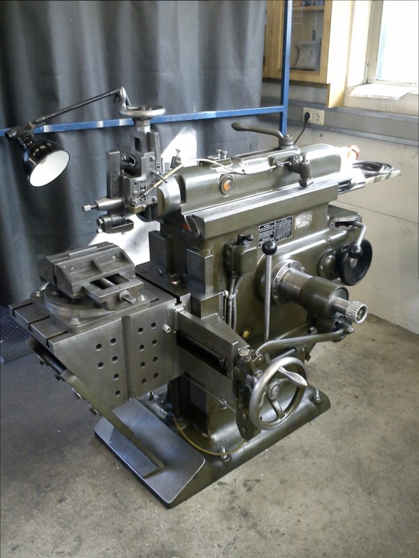
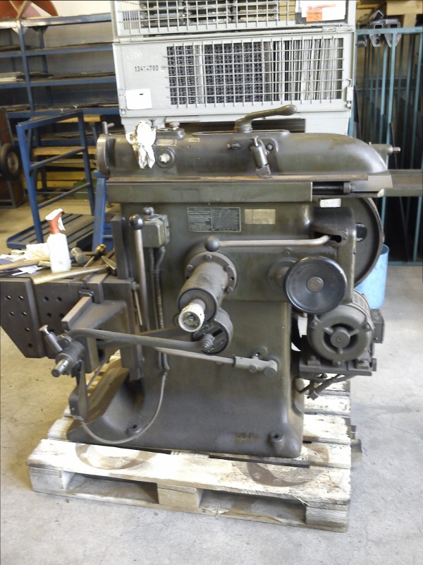
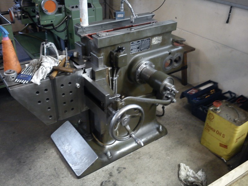
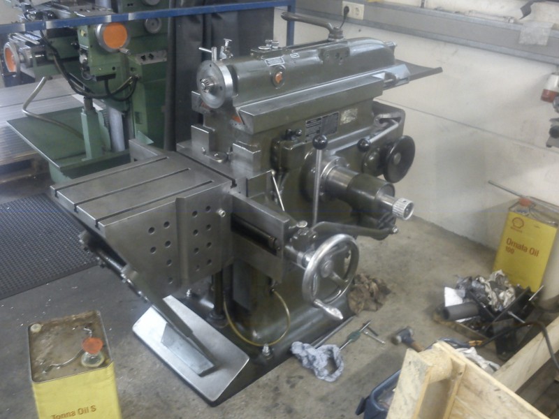
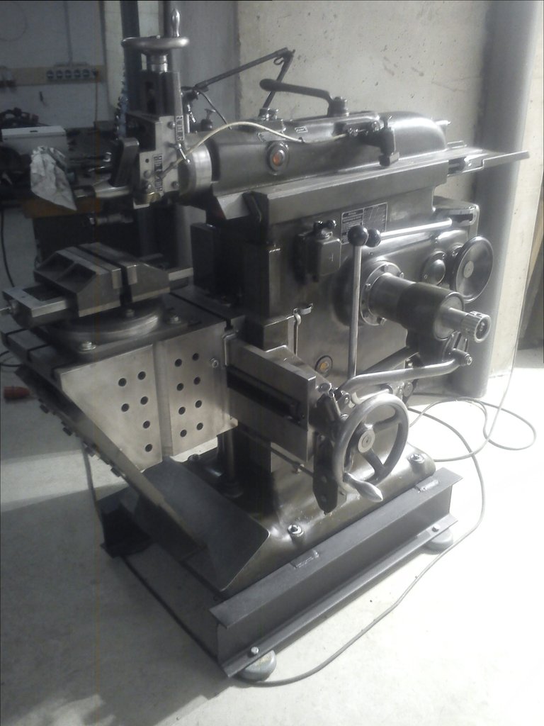
Today it KLOPPed for me too. Because one project is never enough, and through the friendly mediation of mechanobernd, I came into possession of a Klopp 550 high-speed shaper:
But things in order…
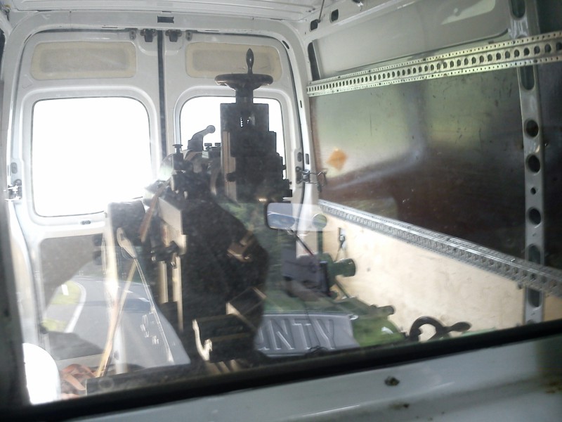
Loading it into the van:
A nice passenger; I lost count of how many times I, as the navigator, turned around to look at it:
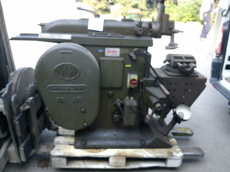
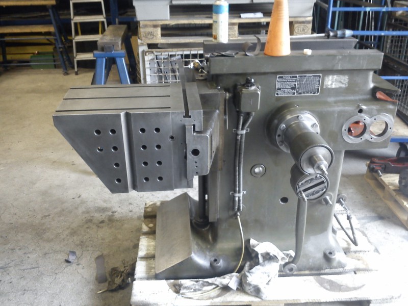
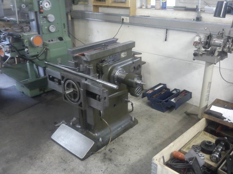
It comes from German army surplus, hence the olive paint, and apparently sat unused for some time, so a thick layer of dust was found on the ways etc. The ram guides – after a thorough inspection that will of course continue over the coming days – unfortunately do show a few signs of wear. Lucky that semester break is on in SH, so I can work on the machine non-stop for the next two weeks.
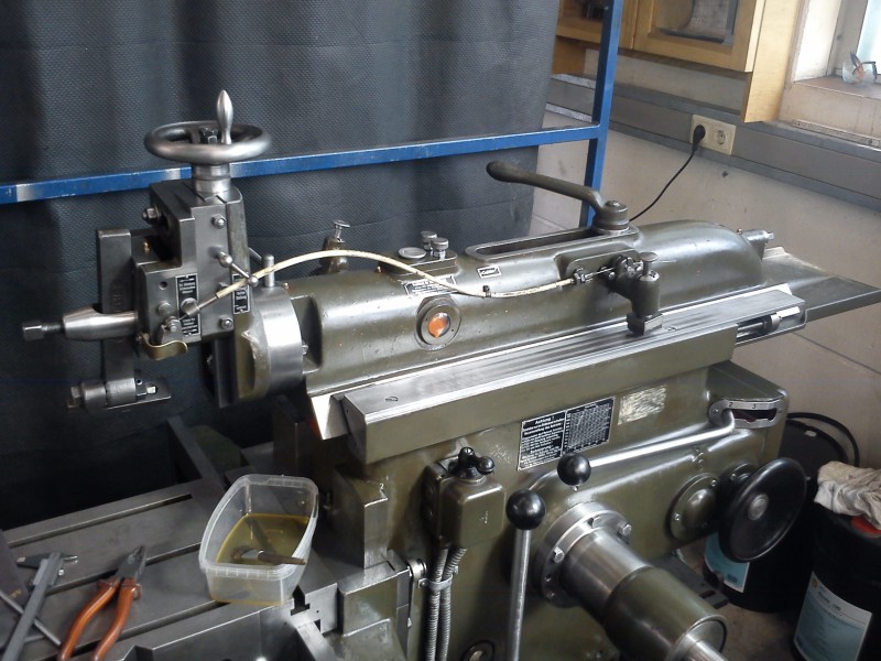
Today I already removed the “smaller” attachments (vise, ram head, clapper box, lamp, handwheels, etc.) so I can clean and adjust them individually at leisure.
This machine isn’t going to be repainted; the original paint is still relatively well preserved and gives the machine a really nice patina :-D
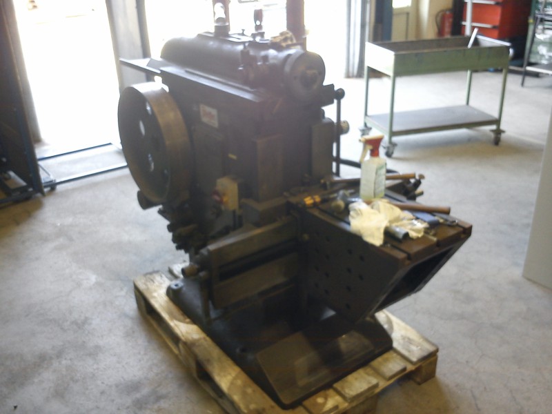
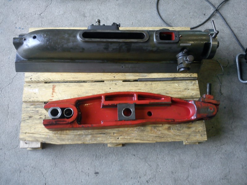
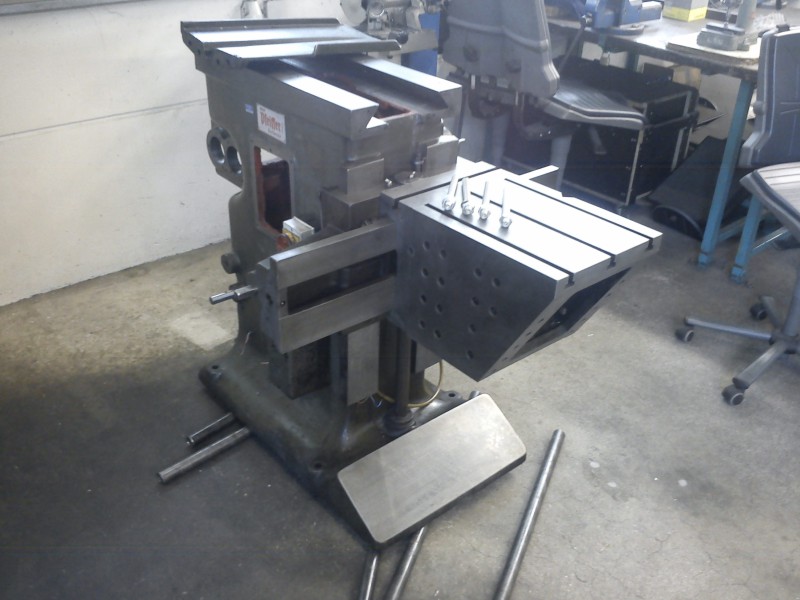
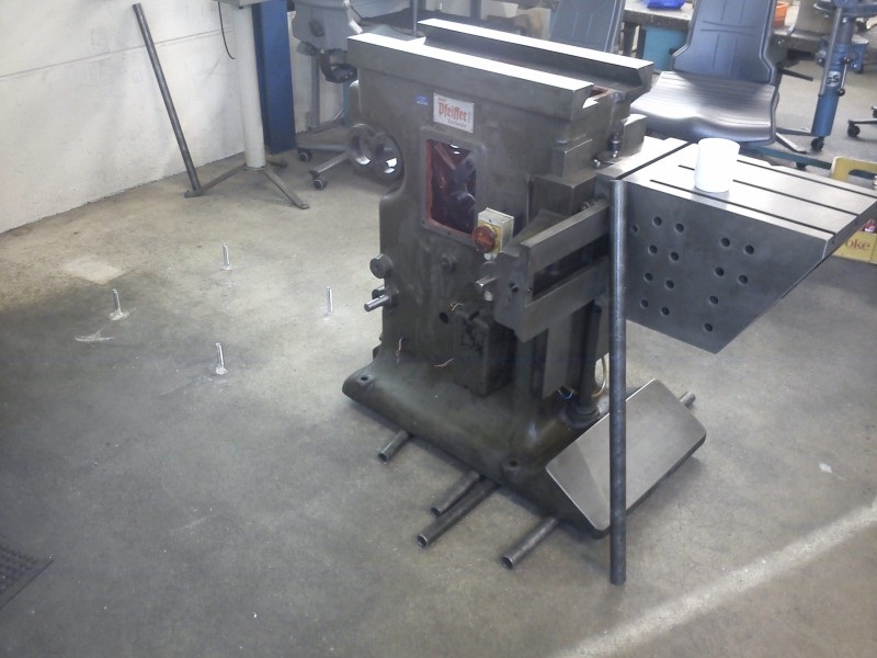
Here the shaper is half-disassembled:
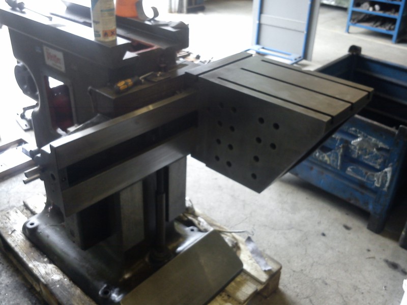
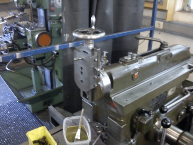
Another nice side view:
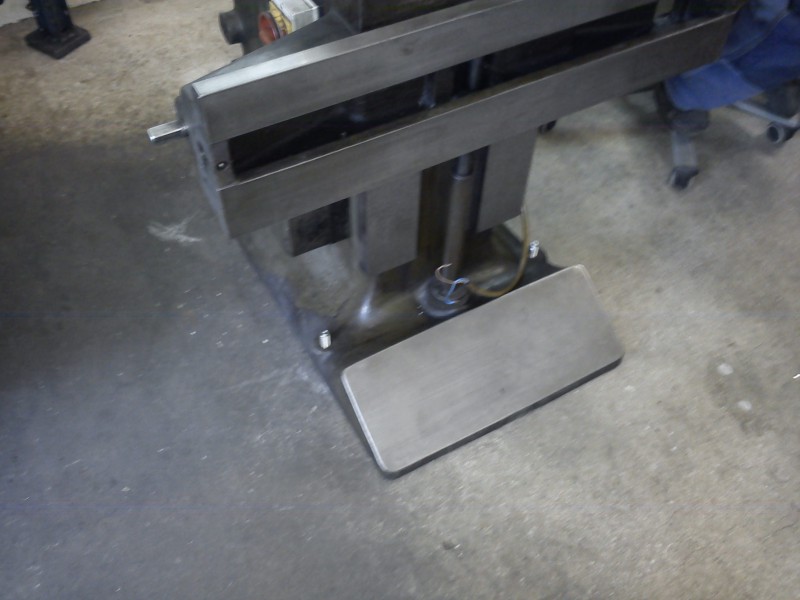
And the front ram guide:
Unfortunately the front wipers – or rather the leather inserts in them – were missing, and the shaper had clearly been run like that for some time. The bottom of the ram guide therefore has rather “nice” scoring marks (photos to come tomorrow).
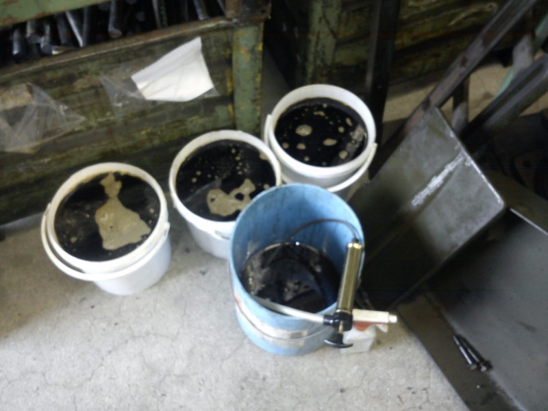
This morning I first pumped out the oil (about 30 L) with a hand pump, as described in the manual:
Then I got to the lower end of the rocker arm and could drive out the shaft on which the rocker arm is guided at the bottom. The rocker arm could then be lowered further into the base, allowing the ram to be removed.
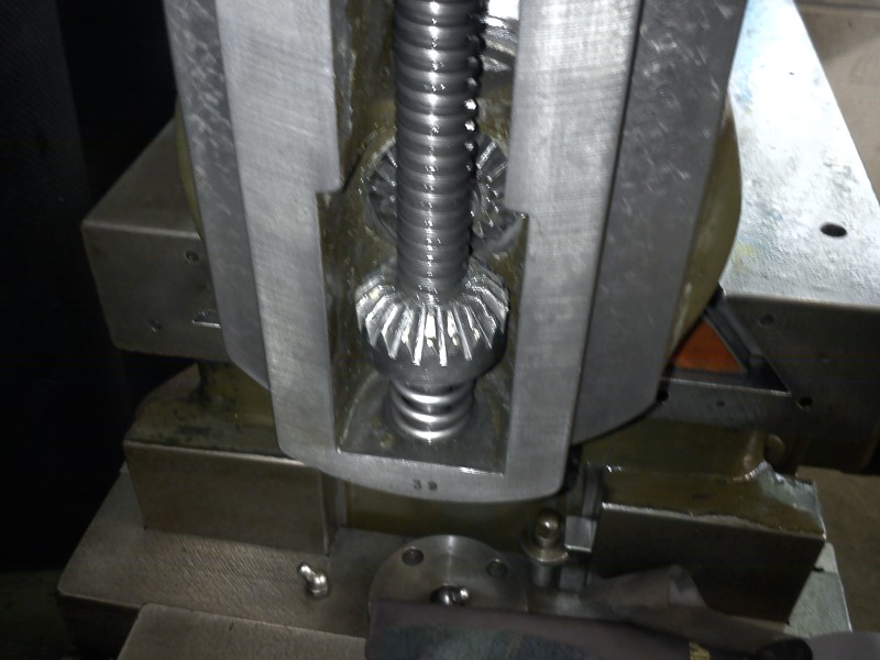
That gave a clear view of the bull gear; the stroke-length adjustment still looks very good – neither signs of wear (scraping pattern still fully present) nor traces of major collisions.
With the ram removed, I could also inspect the central ram guide. Here, fairly heavy galling marks are present. Unfortunately I don’t have the time or skill to re-scrape this guide. I hope that with proper lubrication (the oil reservoir in the ram was dry) and after smoothing the scoring with a bit of abrasive cloth, the shaper will hold up for a long time. Once you know how to remove the ram, you can also do this later when more time is available.

I then drained the oil from the gearbox and opened it. The gears all still look great, only a few chips were found in the oil. Those are probably more from former workpieces than from the machine.
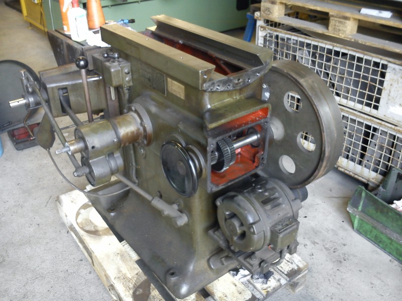
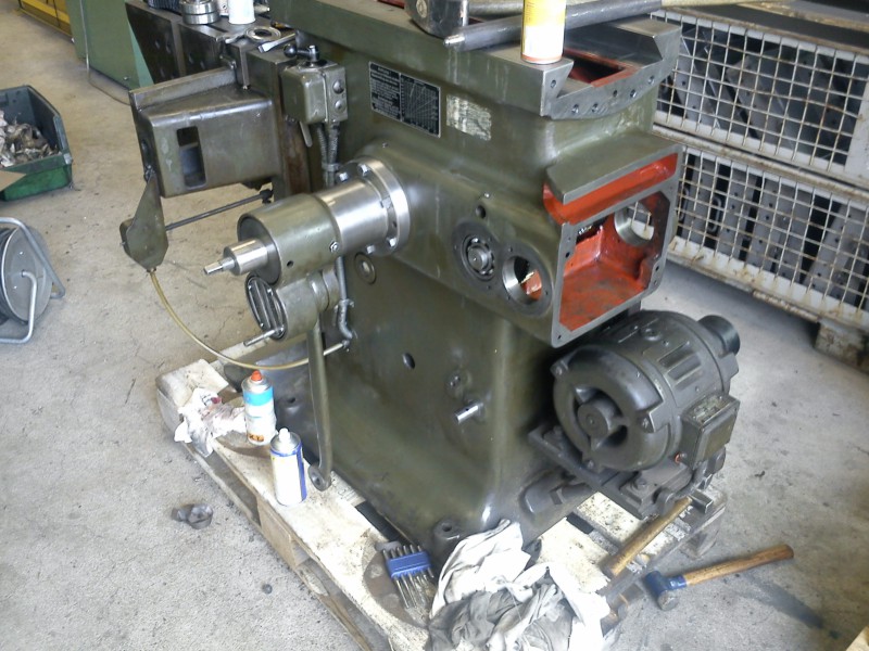
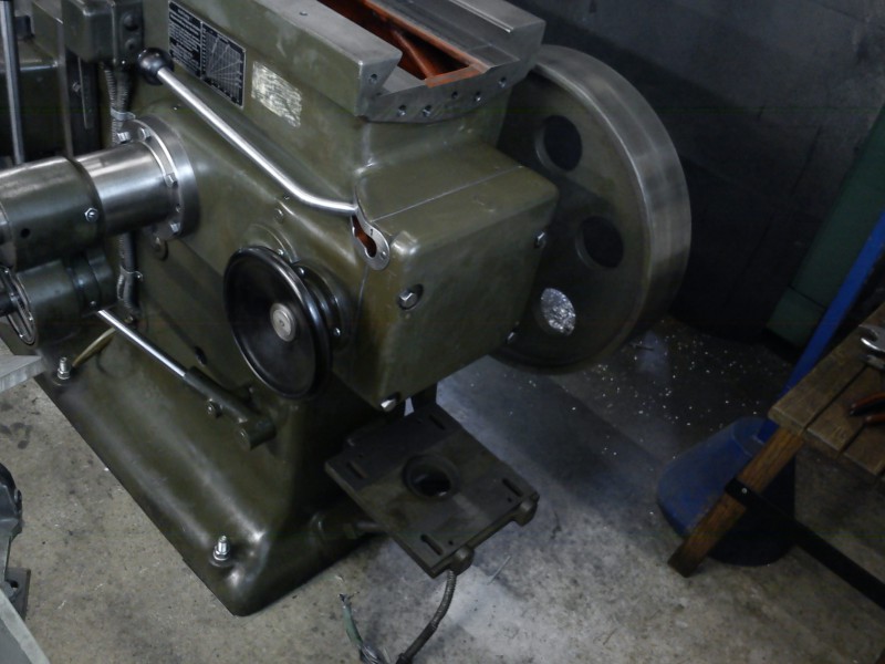
This is what the machine looked like at that point:
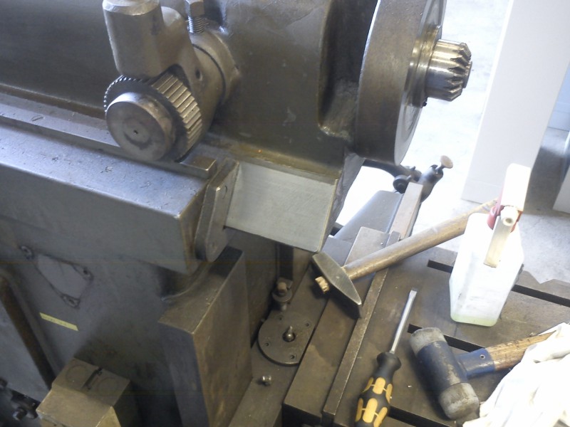
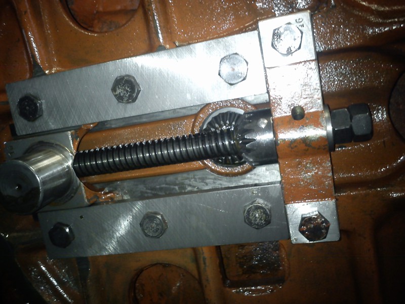
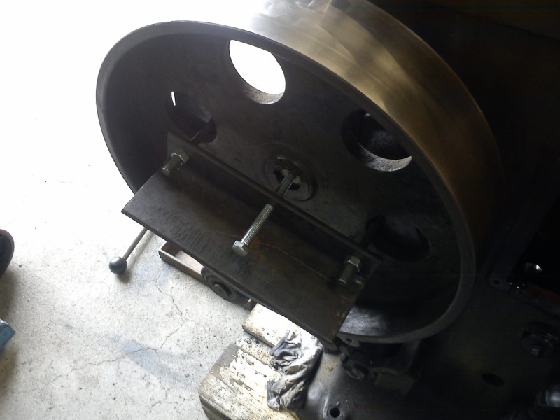
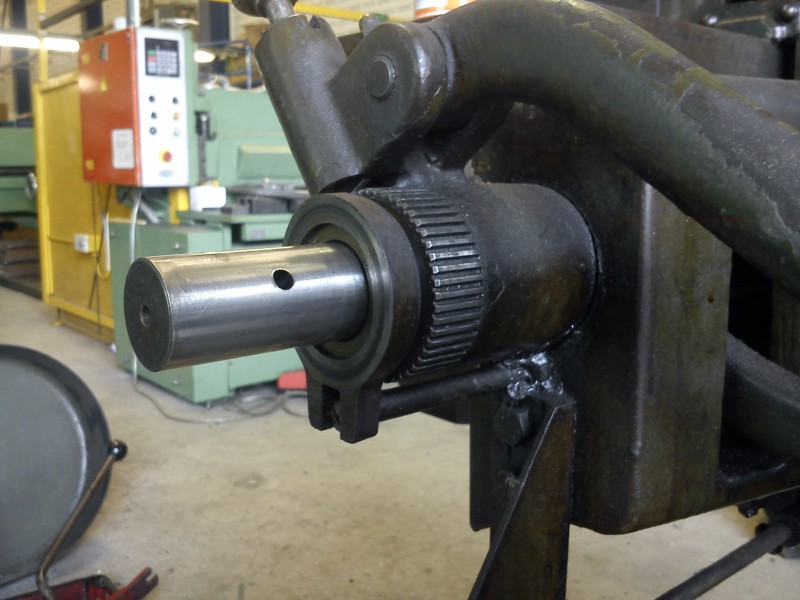
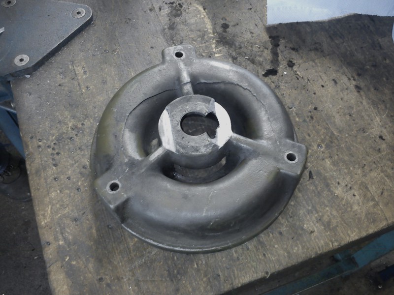
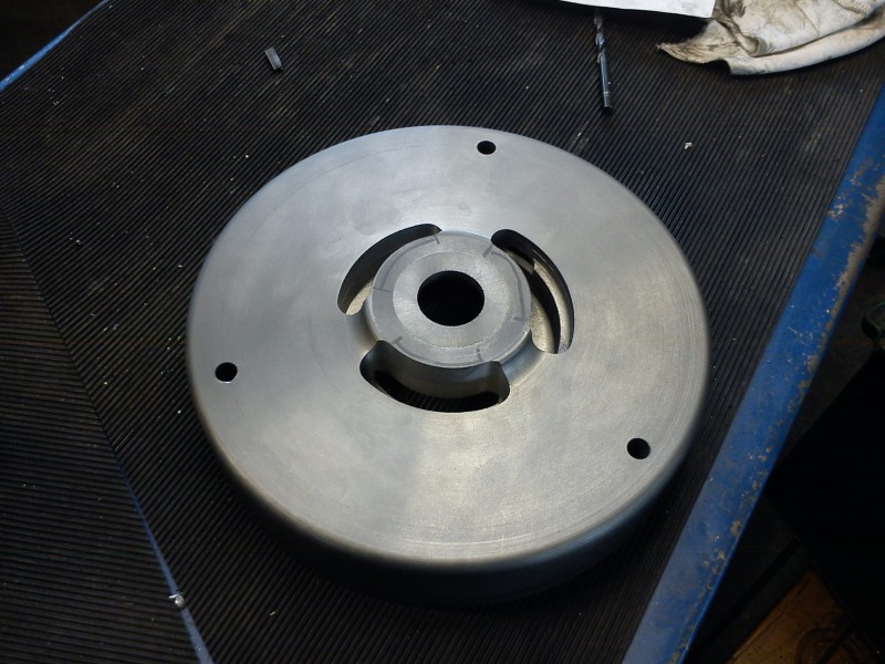
The big flywheel was then sanded shiny and pulled. Unfortunately a suitable puller was missing, so one was quickly improvised:
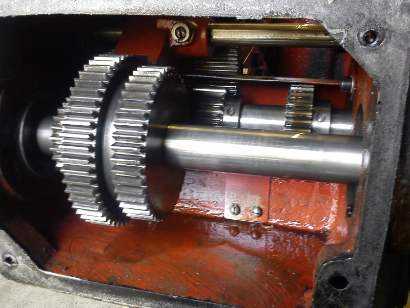
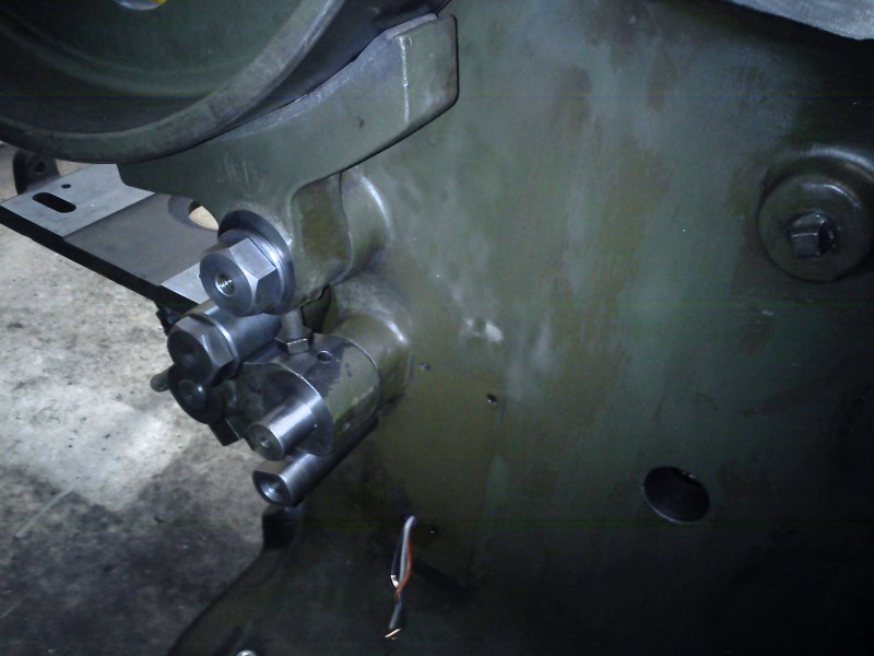
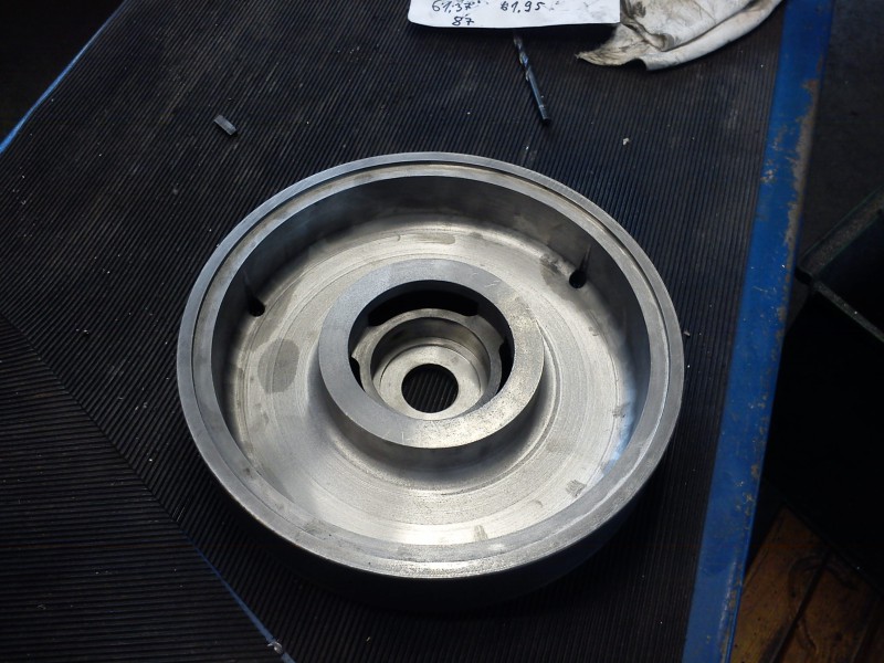
Without the flywheel, the shaft stub looked like this:
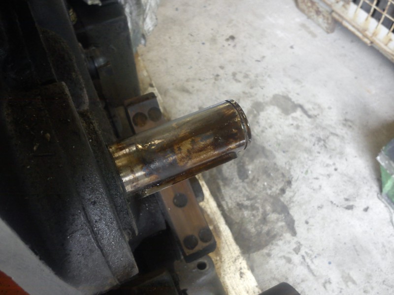
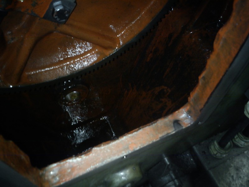
That brought the following dirty detail into view:
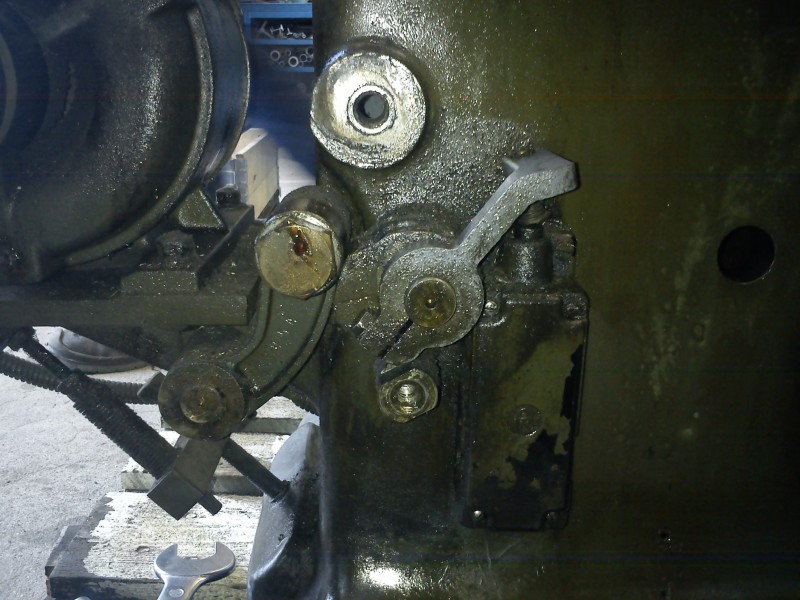
Here’s a picture of the ratchet for the horizontal feed. Fortunately the gear seems hardly worn:
New bearings for the gearbox have already been bought and will be fitted tomorrow with new oil seals. The old ones rattled fearfully. Unfortunately the most disgusting part of the cleaning is also still on the agenda – namely the oil sump under the rocker arm. I’ve already shovelled out the worst of the gunk, but there’s still something in there.
The manual specifies “SHELL Vitrea Oil 100, 68 cSt (9E) at 50 °C”.
I first reluctantly went on with cleaning the outside of the machine.
The reluctance grew once it was time for the inside. Here a before picture:
and after:
The remaining marks are cast iron showing through where the paint has flaked off. Loose flakes shouldn’t be in the machine any more, and all the gunk is finally out.
I then continued dismantling the gearbox to fit new bearings. They are 4x type 6307 (80x35x21). At the same time the oil seals that seal the flywheel shaft are being renewed. Unfortunately I can’t get the second gearbox shaft out, since the gears are pinned with taper pins and I can’t drive the pins out. I’m sure I’m hitting from the right side (verified with callipers), but nothing’s moving even after applying WD-40 and Caramba. I’ve also hammered with a sledgehammer. Tomorrow I’ll try again with heat and a special drift with a hardened tip.
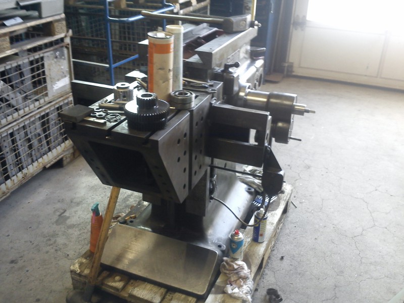
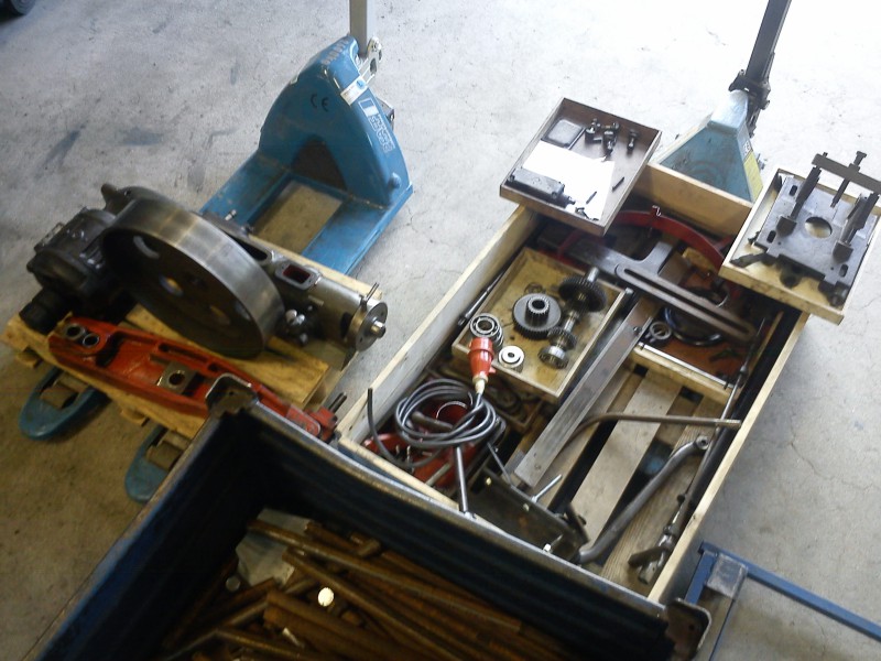
End of the day, the machine looked like this:
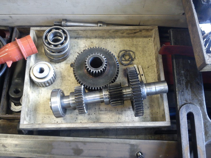
The clamping table makes an excellent shelf for the many tools I need and parts already removed. Here, e.g., is the sliding triple gear from the gearbox:
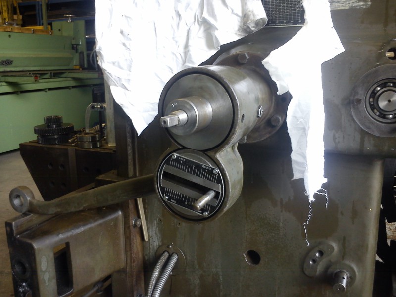
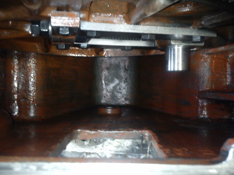
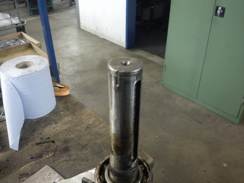
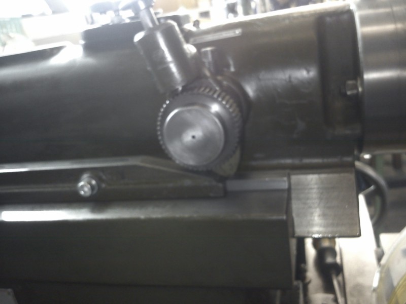
At the top of the ram there’s a small chamber with an oil-level sight glass. I’ve highlighted it here:
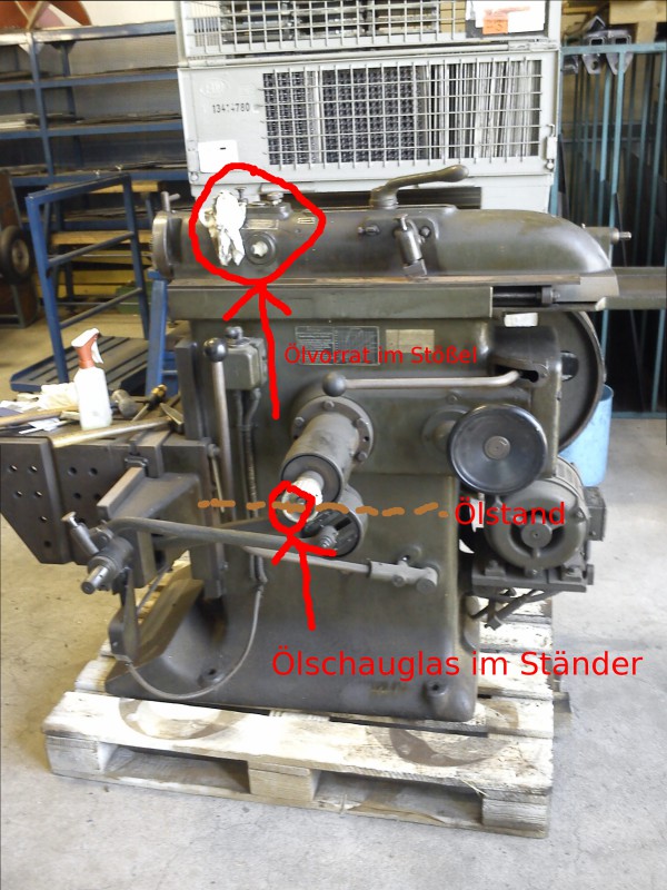
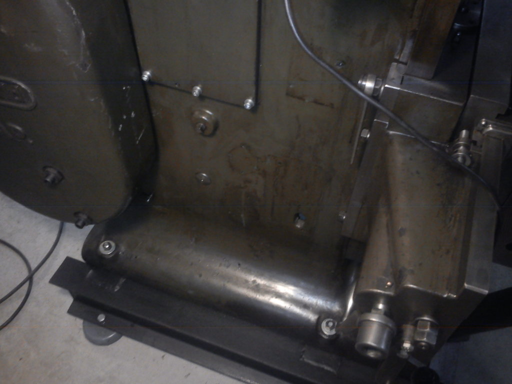
A bent tube leads away from there (through two metering valves in the form of pointed knurled screws that screw into the tube openings). Those are the “valve” spindles that meter oil flow from the ram’s oil chamber to the ram guides. The tube is essentially connected at both ends to the oil reservoir. Roughly in the middle of the ram, the oil can flow through T-pieces to the ram guide. At the centre of the tube length (i.e. all the way at the back, near the stroke-position adjustment; the tube is fairly long) there’s also a hole, so the spindle for stroke-position adjustment is also lubricated. Hard to describe; here’s a picture of the underside of the ram:
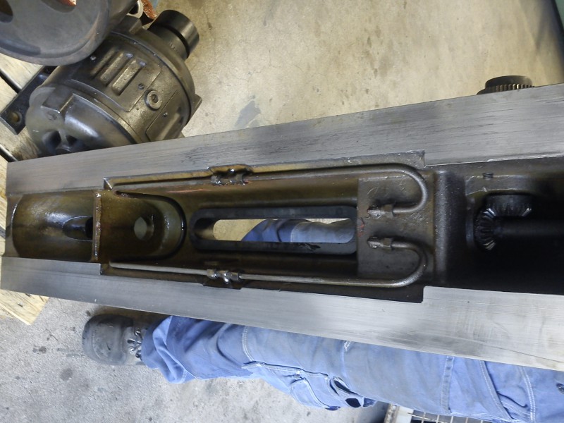
You can clearly see the tube which is connected in a loop to the oil tank, with the T-pieces feeding the guide ( :-) ). At the centre of the tube length (at the far left in the picture, where the oil drop hangs from the tube) there’s also a hole through which oil can flow onto the stroke-position-adjustment spindle. Or maybe it’s just a vent hole or something similar… There’s also a grease nipple, but only for the plain bearing at the end where the square is – not in the middle of the spindle.
Unfortunately my Klopp seems to be too old. In the newer versions an oil pump is presumably built in. The bull gear flings some of the oil up; that gets caught in a sheet-metal “trough” and routed e.g. into the gearbox. The “operating and lubrication manual”, the only document I have for the shaper, mentions a splash lubrication system. Its description matches pretty closely what I found in the machine.
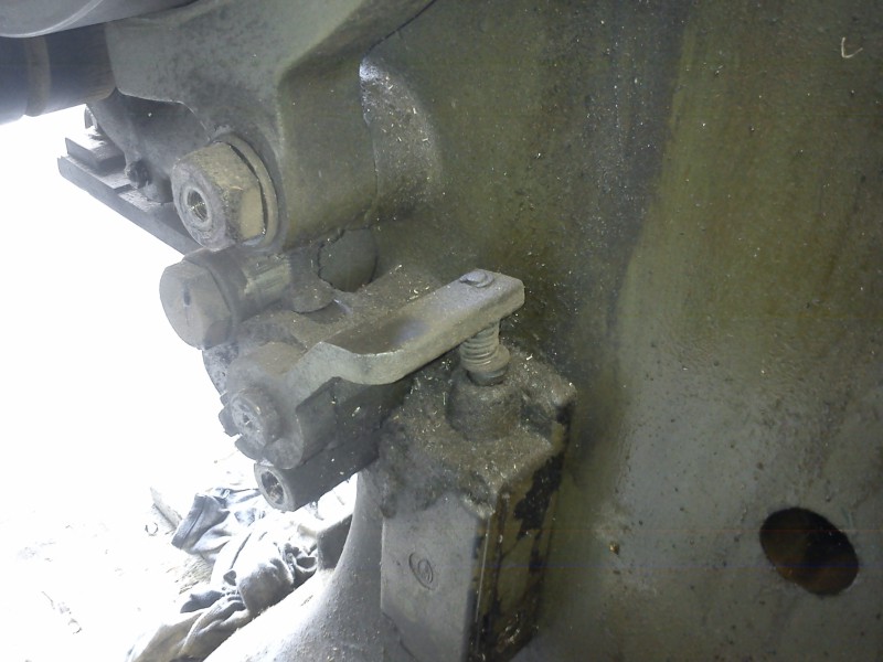
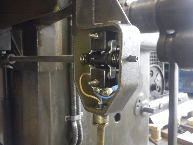
For the upcoming move to the temporary location, I unscrewed the limit switch; here’s a picture of how it’s built:
After yesterday’s troubles with the taper pins in the gearbox, and after they had bathed in sprayed-on Caramba overnight, they came out today without any problem with a big hammer.
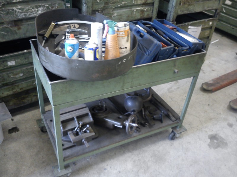
Quite a respectable pile of small parts had also accumulated; here are a few impressions:
The brake / friction clutch was then drowned in copious amounts of parts cleaner. After that, wiping the dirt off was no problem any more:
Next, together with a kind helper, I tackled sanding the table. I think the result is presentable:
It’s fun again to clamp parts and start cutting :-D
Since I currently don’t have space in my home workshop, I’m fortunate to be able to set up and use the shaper for now in the workshop where I’m restoring it. First with a pallet jack (the Klopp was still on the pallet from pickup) to the end of the crane rail:
Then move it onto pipes and roll it to its destination. The anchor rods that will fix the Klopp to the floor are already lying on the table:
After marking and drilling the holes, the anchor rods were glued into the floor with a mounting adhesive made for such cases (similar to mounting foam). Since the adhesive expands and I would eventually want to take the machine home, the anchors had to be glued without the machine standing on top. You can probably see how much adhesive expanded out:
But that creates a problem: how do you now lift the (still) very heavy machine body onto the bolts when the crane can’t reach this part of the hall?
Easy: with a bottle jack, pry bar, U-channel, steel pipes and many helpers, the machine could be put on rails; that way it could easily be moved over the bolts and then, by tipping back and forth and gradually lowering by inserting different pipes, lowered all the way to the floor. Please understand that I didn’t take pictures of this – I was a little under stress at the time ;-) So there it stands now; the table was also taken off to save weight, so the lead nut can also be cleaned nicely.
Tomorrow and over the next week, the cleaning of the small parts and reassembly/adjustment will follow. Fortunately, the workshop’s electrician will also test and certify the machine so I don’t have to worry about that :happy:
At this point I would also like to thank the workshop’s masters and employees most sincerely for the great support and constant openness to questions. Without them an undertaking like this would not have been possible for me. Period.
The machine has been levelled (not literally with a water level ;-) ) and bolted to the floor. I tried to shake it, but the bubble of the machinist’s spirit level didn’t even budge. That should be sufficient for operation :whistles:
I then clamped the horizontal spindle in the lathe and used a wire brush and (with the machine off, of course) a rag to make it a little shinier. The gibs for the table were also cleaned and re-installed. Roughly adjusted, it’s already noticeable that the table runs a bit stiffer on the right side (looking from the front) than on the rest of the way. The scraping pattern is also best preserved there. At some point someone (i.e. me) will have to re-scrape that…
Over the weekend I also took home the ram head with the vertical slide. I think I’ve become addicted to oily, sticky fingers :-)
After a Klopp-free weekend, today I got back into it at full speed :-D
First, I refastened the table and oiled it. The index pins for setting to 0° are also back in:
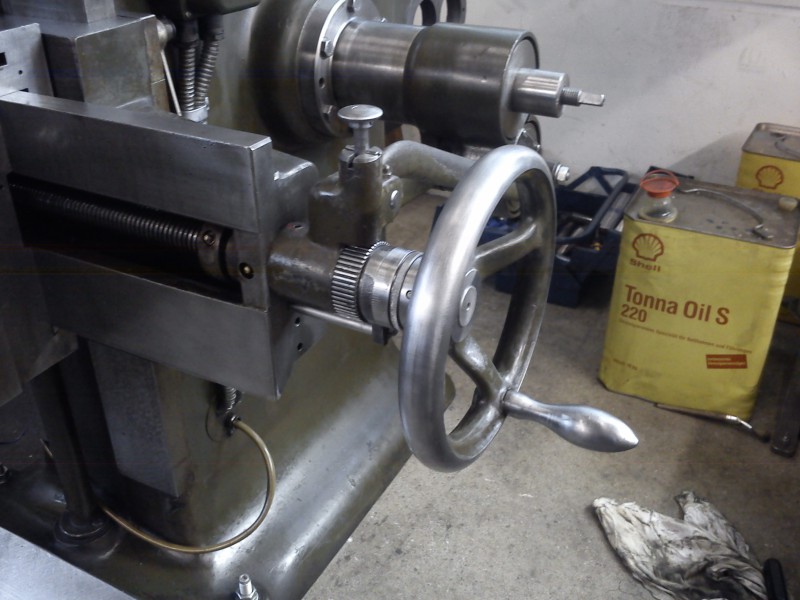
I also refitted the handwheel for the horizontal adjustment, and the ratchet is back in place too:
The first inner shaft, with its gears and new bearings, is now back in the housing. Unfortunately tomorrow I have to be home to make sure the workmen install our new front door the right way around, so I can’t go to the workshop. So no report tomorrow, sadly.
New oil has also been ordered; it should be delivered Wednesday on time.
Quite a lot happened today as well. Unfortunately the day started with me leaving my camera at home :imstupid: :wall: , so there are no photos today. They’ll of course follow tomorrow.
The day began with finishing the gearbox reassembly. The new bearings run beautifully smoothly. I left the outer seals on the bearings (2RS bearings) so the gearbox oil also lubricates the bearings without leaking out. In addition, the shaft on which the flywheel runs is also sealed with new oil seals. The gearbox cover was then also re-fitted. It had been sealed with a black, paint-like substance. I cut a nice gasket from a rubber mat and hope it’ll do the job for now.
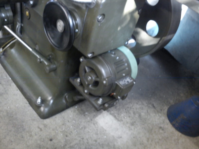
Then the black handwheel for manual turn-over was made shiny (= shiny-black since it’s Bakelite) and re-mounted. The levers for the clutch and the gear shift were also polished and re-mounted. Next, I reassembled the motor cradle and brake mechanism.
Then it was the motor’s turn – I opened it up. The inside was vacuumed. Unfortunately the friction wheel wouldn’t pull off easily; Caramba is working on it overnight – let’s see if anything moves tomorrow.
Oh, and 40 L of fresh oil arrived today as well.
First, a few pictures showing yesterday’s reassembly:
I had drowned the motor shaft in Caramba yesterday so I could pull the rubber wheel today. Unfortunately I had no luck this morning either, and got a bit more forceful. The end of the story: ka-pling, and the end bell had a crack:
The small puller was too small and the big one I then ended up using had jaws too thick to grip between the motor and the hub, so I put the end bell (supported by flat steel) in a large hand-lever press and gave it some.
The saw marks at the bearing seat are from later, when the puller had to have room to grip the steel hub of the friction wheels. Annoying… :-(
Unfortunately the inner part canted on its way out, so the part can’t even be straightened stress-free. What you can’t see in the photo is a second crack at one of the mounting holes in the outer cylindrical section, which widens out below. You could possibly have welded or brazed the cover, but not stress-free enough for me to give it another 20+ years on the motor – especially since the front bearing might have suffered from the distorted mounting position.
Anyway, the shaft is out and so are the rubber wheels. Here you can see the culprit that held the wheels in place:
Apparently during the original assembly ~50 years ago a chip got into the groove for the snap ring and was drawn in. With a large puller I borrowed from a neighbouring workshop, the wheels finally came off.
Then it was easy to also pull the old bearings. The new ones have already been bought (1x 6205 and 1x 6206; both 2RS):
For the broken end bell, a continuous-cast round has been ordered; it’ll arrive Tuesday. What else are a milling machine and a lathe with dividing head and faceplate for?
I also polished and oiled the gib for the ram guide; the connecting rod is back in the machine and waiting for the ram, which I started cleaning towards the end of the day.
The electrician also stopped by briefly to assess what needs to be done:
- motor protection switch
- no-volt restart protection
- pushbutton switches for the clutch/brake lever
- possibly a new control box
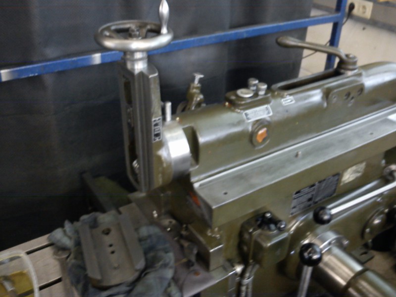
I finished cleaning the ram today. Pleasingly, both oil lines (or rather the entire one) were still clear, so I didn’t have to remove them to blow them out. I also cleaned up the vertical feed a bit; you can see it here:
The ram could then be re-installed. The connecting rod was already in place yesterday. Unfortunately you can’t get the ram in or out unless you pull the shaft on which the rocker arm is guided at the bottom. To slide the spacers (which keep the die-block in position) onto that shaft, you unfortunately have to crawl into the machine arm-deep up to the shoulder :-D Caused much hilarity among the colleagues ;-) The oil reservoir in the ram was then also filled with slideway oil.
This is starting to look like a shaper again, isn’t it?
The shiny areas were mostly worked with abrasive cloth; for the ways I used an oilstone. For the grease crust, alternating cold cleaner and a substance called Multi-Oil helped, each combined with plenty of elbow grease. There wasn’t much rust on it. Most of it was just dirt and surface rust that came off just from looking at it.
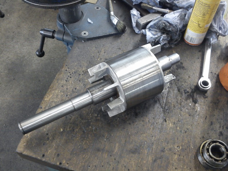
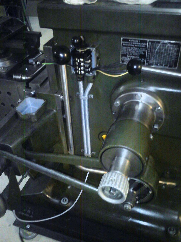
The drive of the ram-head slide works as follows:
There’s a ratchet on the side of the ram that gets “tripped” on the return stroke. Through a damped shaft with two right-angle gears (one for redirecting from across to along the ram, and one in the connection between the vertical slide and ram), it drives the vertical spindle on the ram head. The gear you see at the ram nose is part of the second gearbox mentioned. It can be flipped forward and back via a lever, so the feed can also be disengaged.
The ratchet rides up against a “ramp bar” that can slide longitudinally on the ram. That’s just a piece of flat steel that gets thinner toward the front (over the front 50 mm it drops about 10 mm from the top edge). That way, on the ram’s return stroke, the ratchet “climbs” this “ramp” and trips at a particular point. At the bottom this ramp bar is slotted lengthwise and can be locked in any position on a fixed piece of flat steel by means of clamping screws. That lets you use the vertical feed at any stroke position and length.
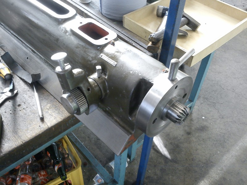
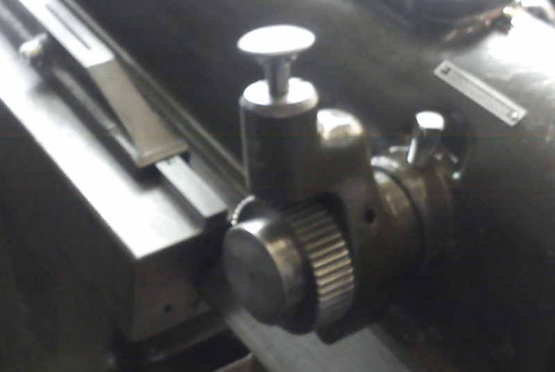
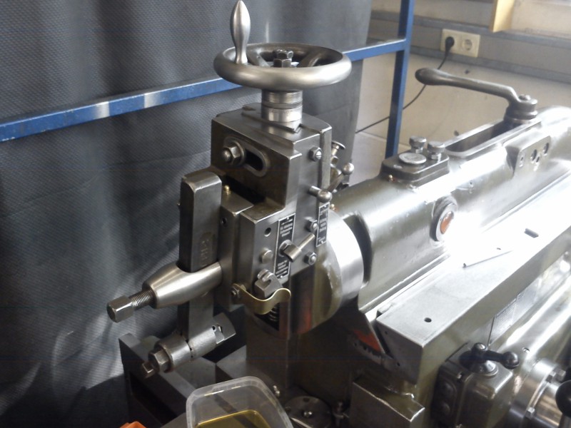
Here are two photos of the vertical feed I re-mounted today:
The ram-head slide (or whatever it’s called) was up next, or rather is now up:
Unfortunately the bevel gear on the spindle is a little worn, but I think it’ll still work:
Here you can also nicely see the scraping on the way, which in my opinion is still pretty respectable for THAT age.
Then the slide on top and that was it:
The clapper box is back on today:
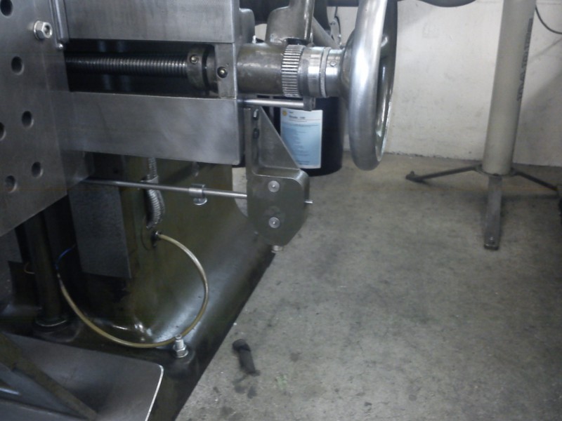
The limit switch for the horizontal feed has also been cleaned and re-mounted:
The lamp holder is back in too:

I still have to do the lamp itself; coming up…
Then it was the tool lifter’s turn – or rather the linkage that goes with it:
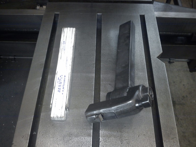
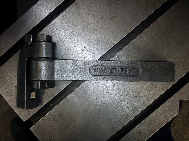
Here’s the tool holder again (a Comet FH-2), unfortunately the only one I have at the moment. On the upside you can clamp 12x12 mm HSS tool blanks in it, which is a very economical way to work. For size comparison, a small box of matches (GMS) next to it:
Once everything (apart from the motor and lamp) was back in place, oil was filled in again.
And here’s the whole machine in all its glory, hence in the highest admissible resolution (modem users may stone me):
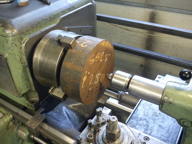
The cast round arrived today, dia 250, l 80, GG25 :-)
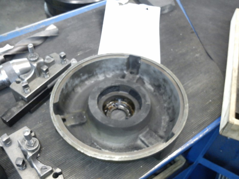
Today I first finished cleaning the motor’s stator and the rear end bell:
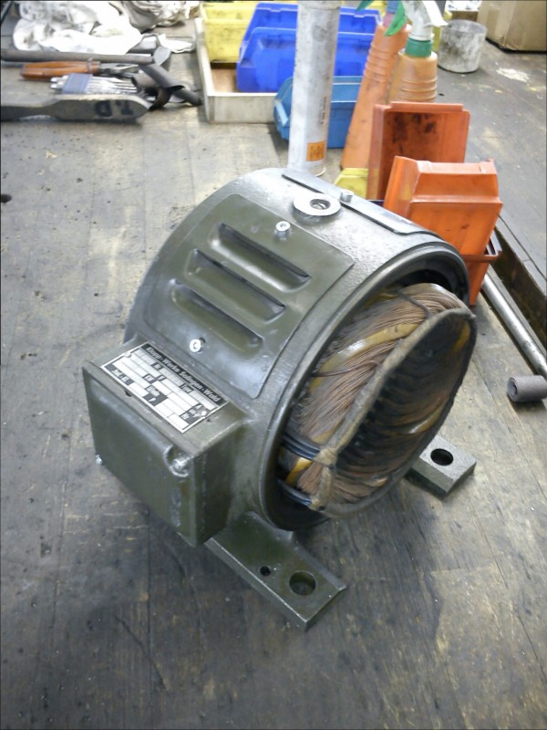
Then I started on the front end bell, which I have to make from scratch.
Motor end bell #
The story starts with 28.7 kg of GG-25 in the form of a round, 250 mm diameter and 80 mm long:
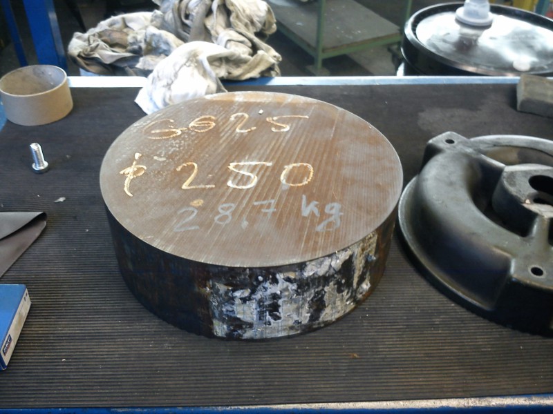
I bought the round (dia 250, l 80) from Richter Kiel for EUR77-something.
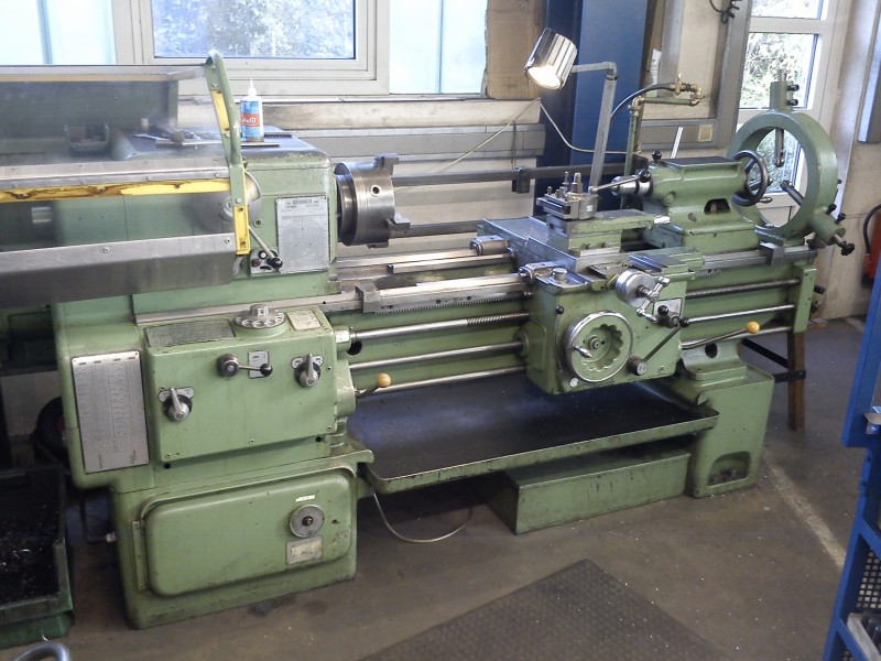
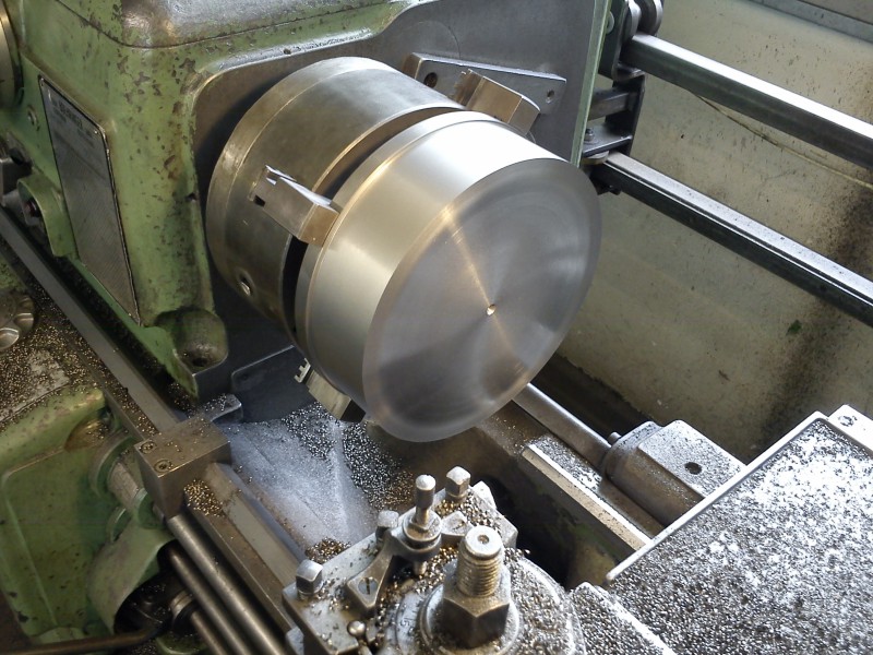
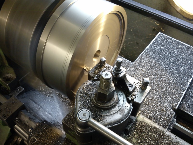
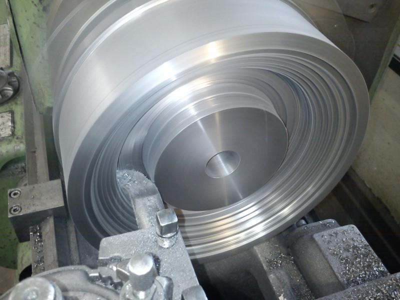
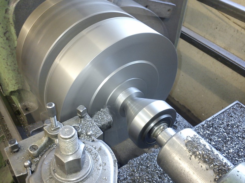
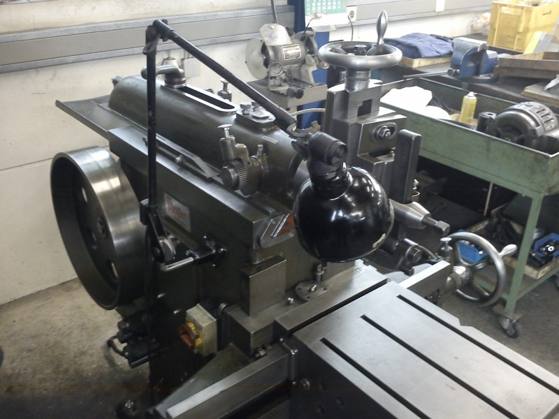
BTW, this is the machine I’m making the end bell and other parts on:
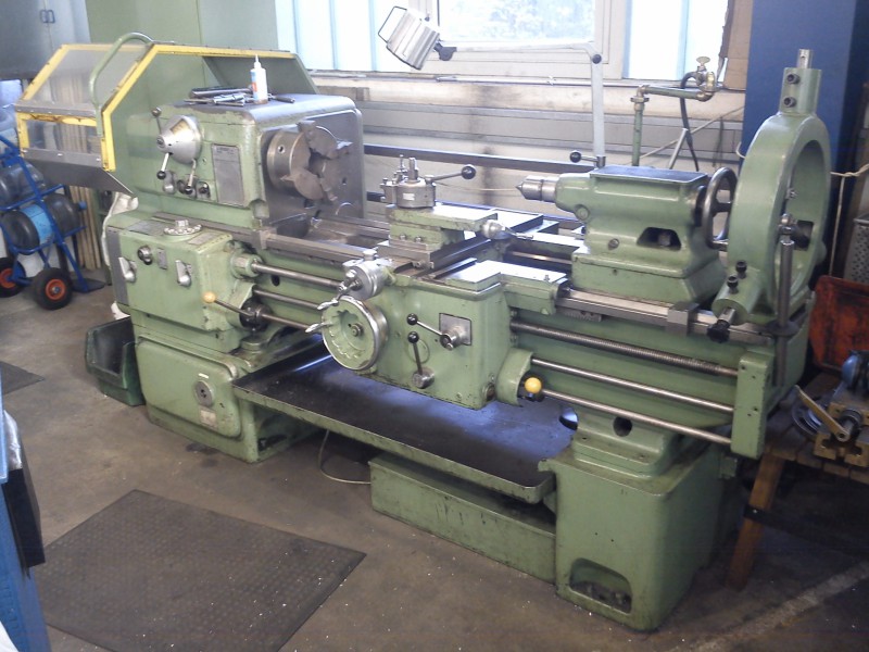
I fitted the big 250 mm four-jaw chuck and clamped the blank:
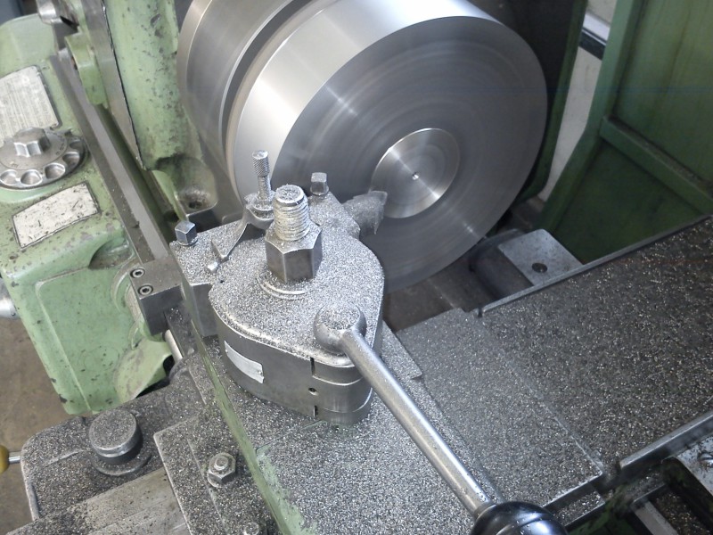
First, face the outside:
The end face too:
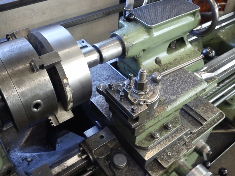
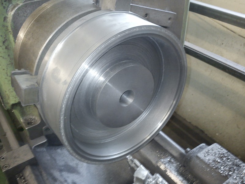
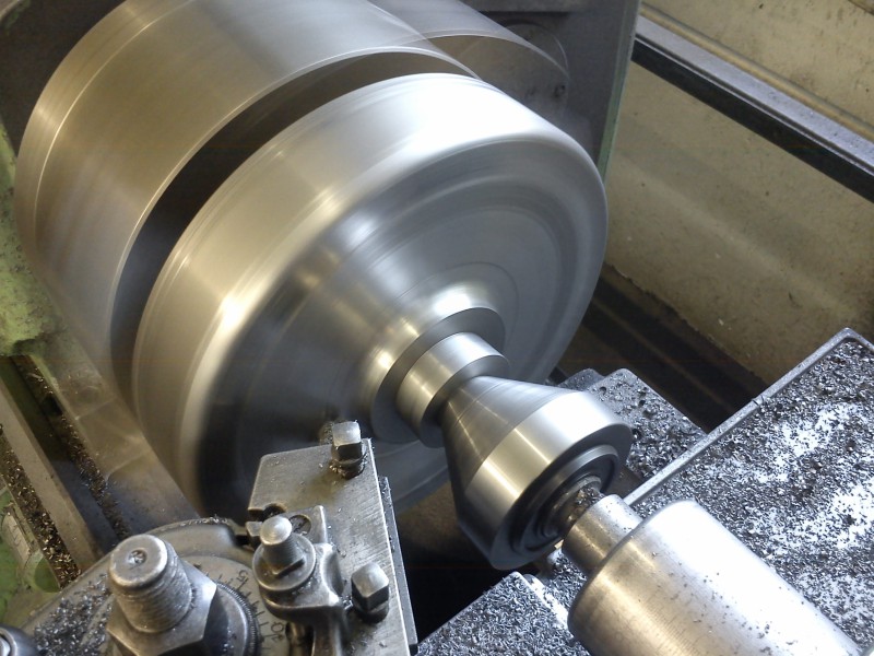
Then flip it, face the shoulder and the other end:
OD finished:
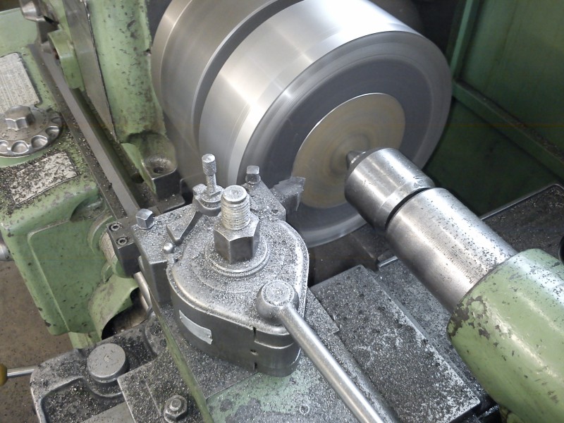
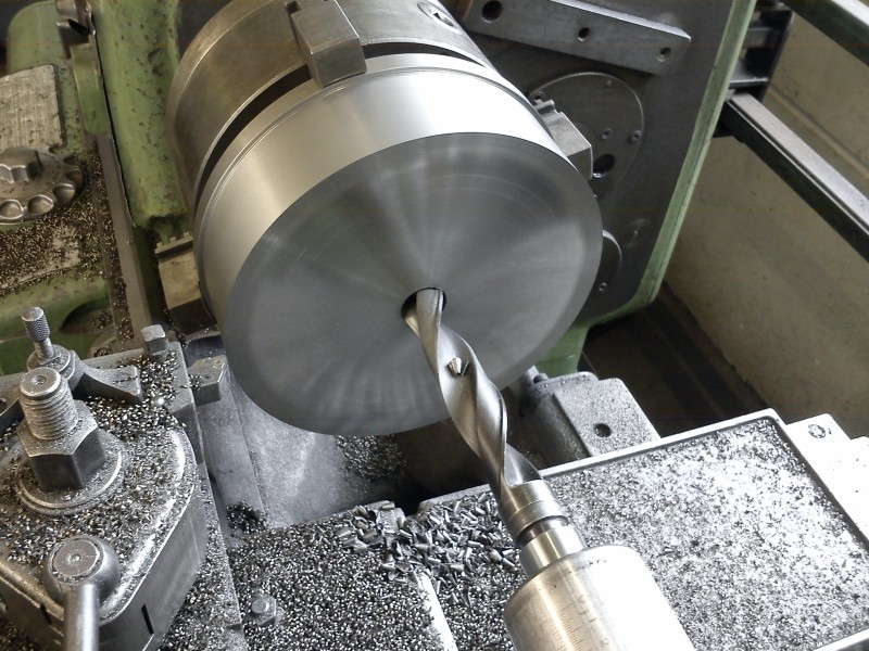
Drill through; don’t worry, I started with something smaller:
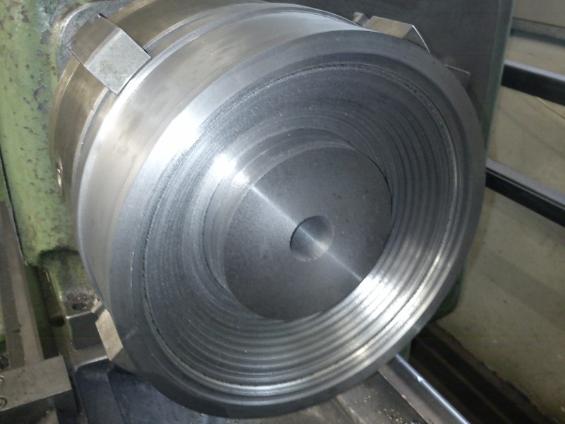
Bore out:
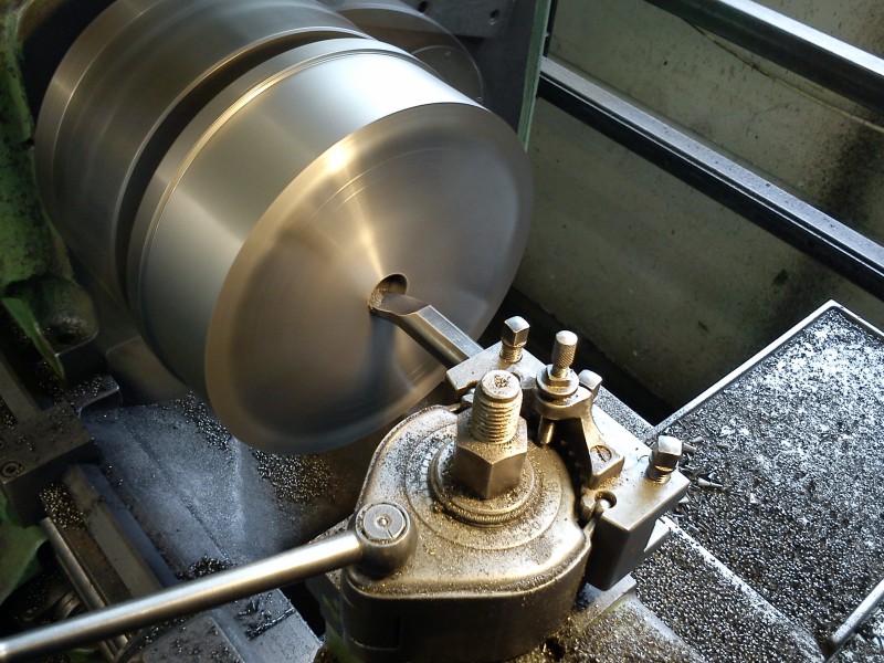
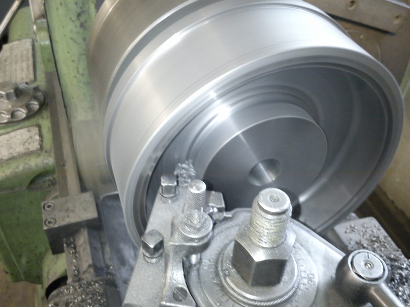
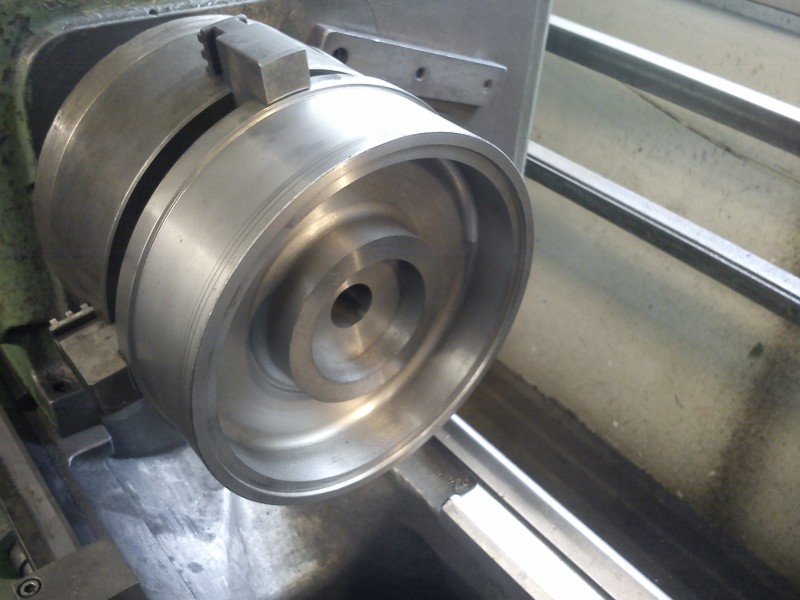
Prepare the housing fit:
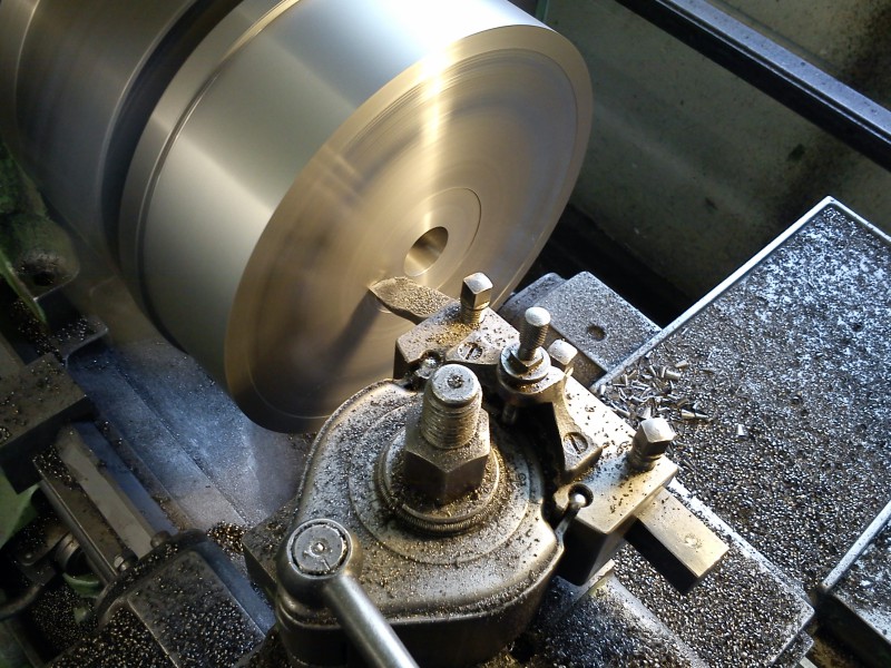
Face the shoulder where the ball bearing will sit later:
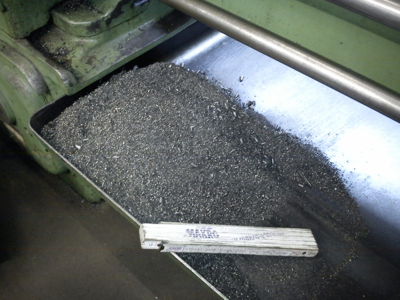
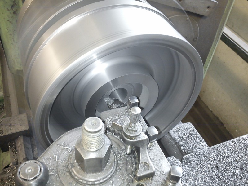
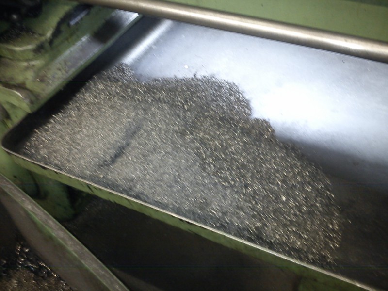
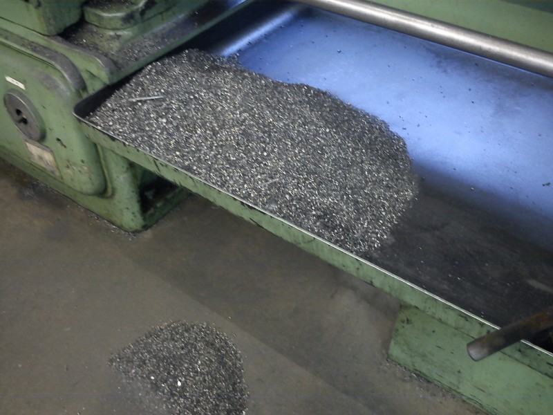
A look at how many chips have flown / sprayed today:
This is what I’m aiming for:
Take-away: cast iron is always nasty to turn, but I hadn’t dealt with it in these quantities until today. A new challenge…
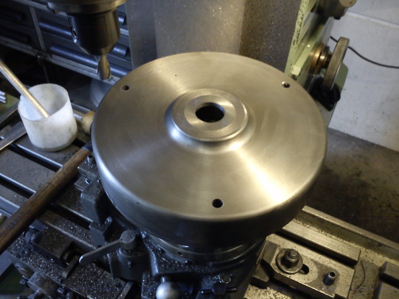
The inside of the cover, including both fits, I’ll do in one setup (the current one) on the lathe. Then the part goes inside-down onto the rotary table on the mill, and there I’ll mill the entire outside and the ventilation slots.
Today I went on to clear the space for the windings and to make the outer housing fit. It started with putting a step in with a parting tool, then working the space out from inside outward with a boring bar:
The corners were then re-worked with an 8 mm radius form tool to avoid cracks in the casting from too-sharp corners:
The recess that will later be milled from the outside for the ventilation slots:
A few more chips made:
End-state for the weekend; on Monday the bearing seat will go in and then, after a few chamfers, off to the milling machine:
In the original setup, the bearing seat was turned:
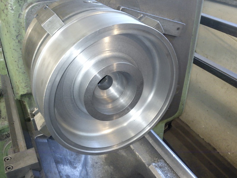
Then test-fitted: the shaft turns without trouble and doesn’t rattle; the cover goes onto the housing snugly:
Then re-clamped and turned to length:
I used the tailstock despite the short overhang, because the inside of the cover was already bored out. I therefore didn’t tighten the jaws fully so as not to push the “wall” inward. It still has 10 mm of thickness, but better cautious than re-doing. Also, I had 20 mm of stock to remove on a 250 mm OD. I didn’t want to be doing that until tomorrow, so I gave it a bit of gas and rather worked with the tailstock.
A few radii always look better:
A few more chips made; that’s it from the lathe:
On the mill, three mounting holes were drilled:
Ventilation slots milled; unfortunately I misjudged the wall thickness on the first one and milled too far outward – but it’ll work:
The same from inside:
Tomorrow I’ll relieve the inside of the mounting holes (they sit half-in-the-wall and the drill drifted a bit) and countersink them; then a bit of paint and the part is done.
So, the part is done.
I just made the last reliefs for the mounting studs and test-fitted the cover:
Fits!
Then take it off and apply Reseda paint (just as a starter, so I don’t have to repaint it during the eventual full repaint). It also doesn’t stand out at the moment, since in operation the flywheel and a huge cover sit over it.
With the new motor end bell now done, I fitted the felt wipers I had kindly received from the forum member “Tyler D.”, and cleaned and re-fitted the lamp:
Towards the end I also got started on the vise; it’s already disassembled, but nothing presentable cleaned yet. It’s the last part still needing to be relieved of rust and dirt.
What happened today:
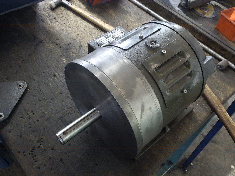
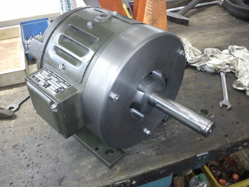
Motor installed: (yes, I know that the colour of the machine clashes stylistically with the cover)
Vise cleaned and installed:
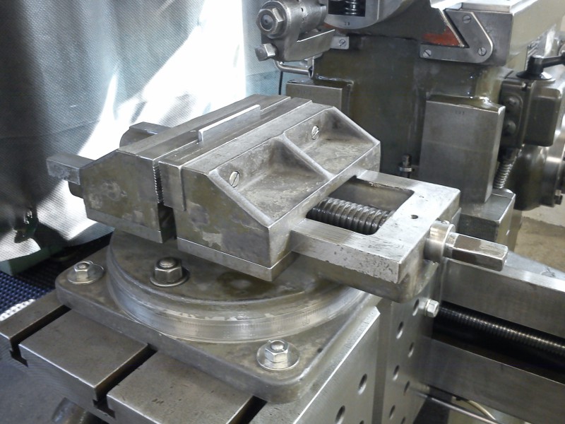
Then I did a few strokes by hand: the machine works in principle, but because of the cutting speed, which is non-existent by hand, the surface finish was rather modest.
Electrics still missing – hopefully tomorrow:
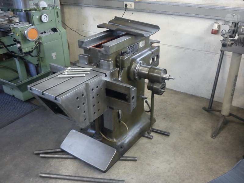
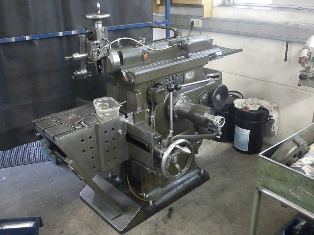
So there it stands now, my Klopp:
May it serve faithfully!
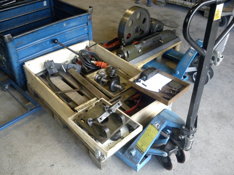
These parts were left over after the work:
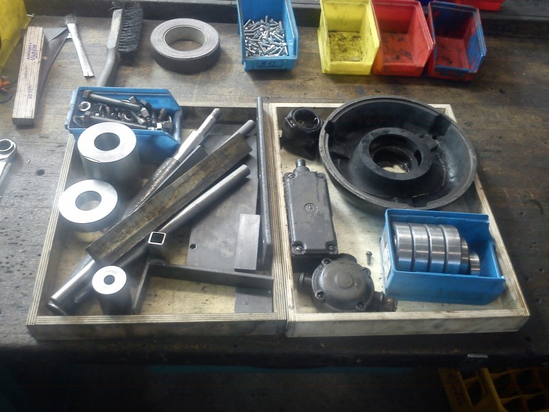
among others: old bearings from the gearbox and motor; flywheel puller; hardened mega-drift for the taper pins in the gearbox; bushings and rings for pressing in the new gearbox bearings without distortion; fixture for gluing the anchor rods vertically into the floor; old electrics; old, replaced screws and other fasteners; the broken motor end bell, etc.
Vertical feed #
On a forum member’s request, I made a drawing of the bar for the vertical feed and don’t want to keep it from you. I used Inventor 2009, in case there are version compatibility issues.
Vertikalvorschubleiste_Inventor.zip
Extended documentation #
I received yesterday from a kind eBay member a copy of his documents for a Klopp 550 he was selling :-D So you can also benefit from it, I made some scans and packed them, together with the operating and lubrication manual, into a single PDF:
What’s new:
- nicer cover pages
- wiring diagram
- machine card
- shaper tools from Hauser & Ruppert (catalogue pages)
- what is, in my opinion, a more sensible page order
Move #
After half a year of nothing happening here, I’ll continue the story of my Klopp 550.
For personal reasons I had to move in October last year, and so did my shaper. By chance I got wind of a small museum in Kiel, where I now live, in whose workshop I can store the machine. As a side effect I once again have a real workshop available (a student flat isn’t ideal for chip-making).
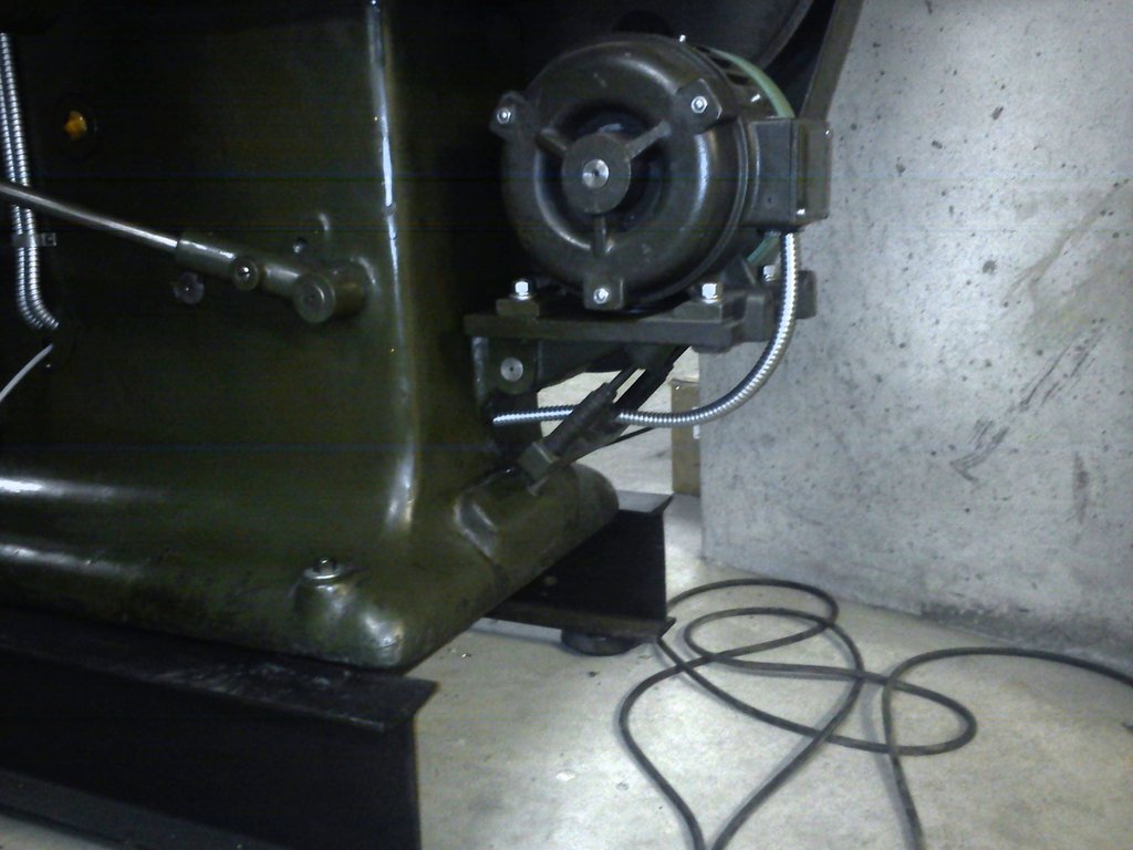
First, I welded together a stand for the Klopp so it can be moved with a pallet jack if the need arises:
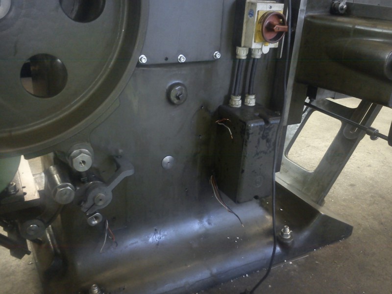
Then I tackled the last thing on the to-do list (before re-scraping all the ways) – namely the electrics. I started by ripping out the old stuff without much ado:
and bought new parts:
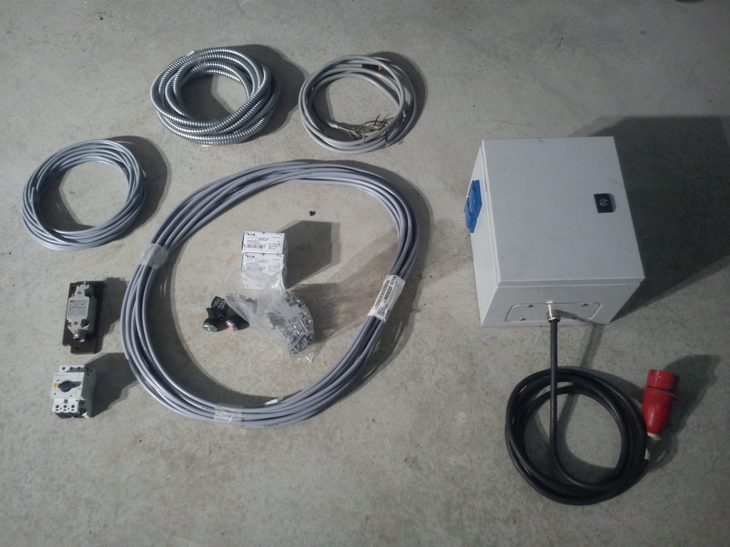
Then crimped on the corrugated conduit (you can even get it at the big C :o ) and pulled the cables through:
Next was the wiring of the control panel, which I just finished:
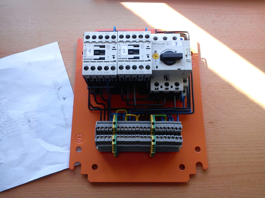
This goes into a small electrical cabinet. I modified the original circuit somewhat: there is now a no-volt restart protection, a second outlet switched together with the motor (whateverforitsworth ;-) ), and contactors that shouldn’t start buzzing for the next 10 years – plus, of course, cables whose insulation won’t fall off if you look at it sideways.
For those interested, here’s the new wiring diagram:
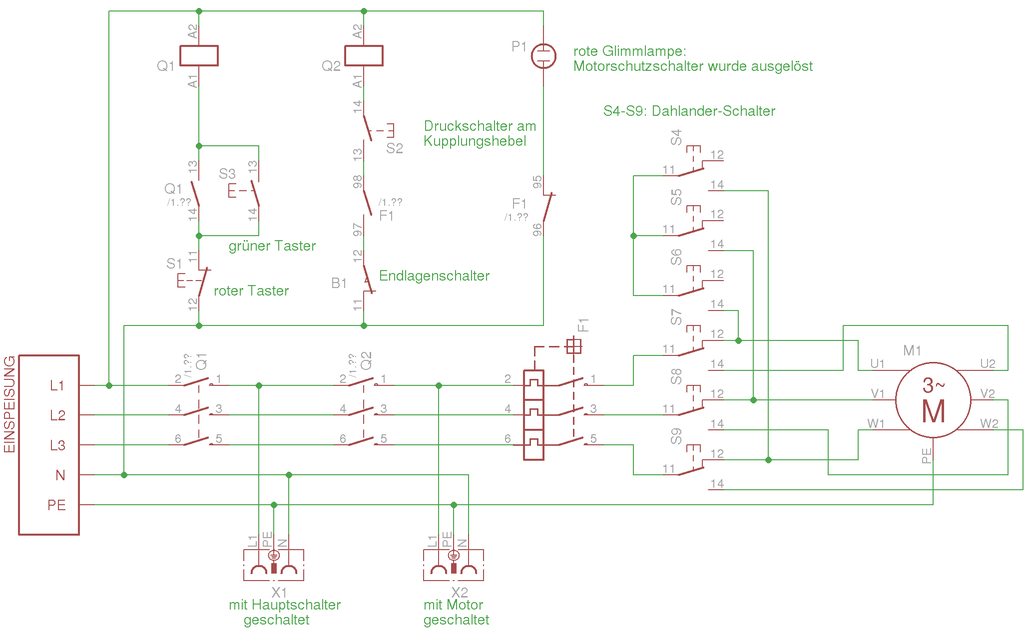
Before I had completely dismantled the electrics, I couldn’t resist hooking up a three-phase cable directly to the Dahlander switch and running the shaper. I have to say, this thing commands considerable respect! But oh, this little machine sure makes chips…