Deckel FP1 #
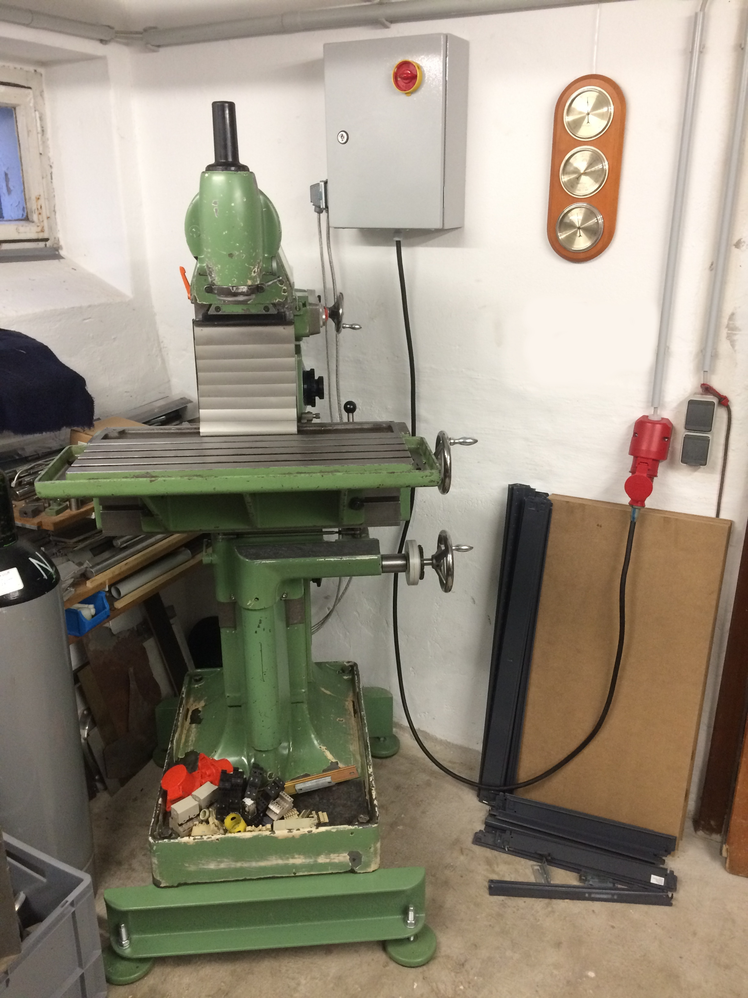
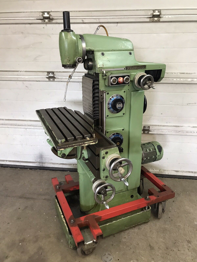
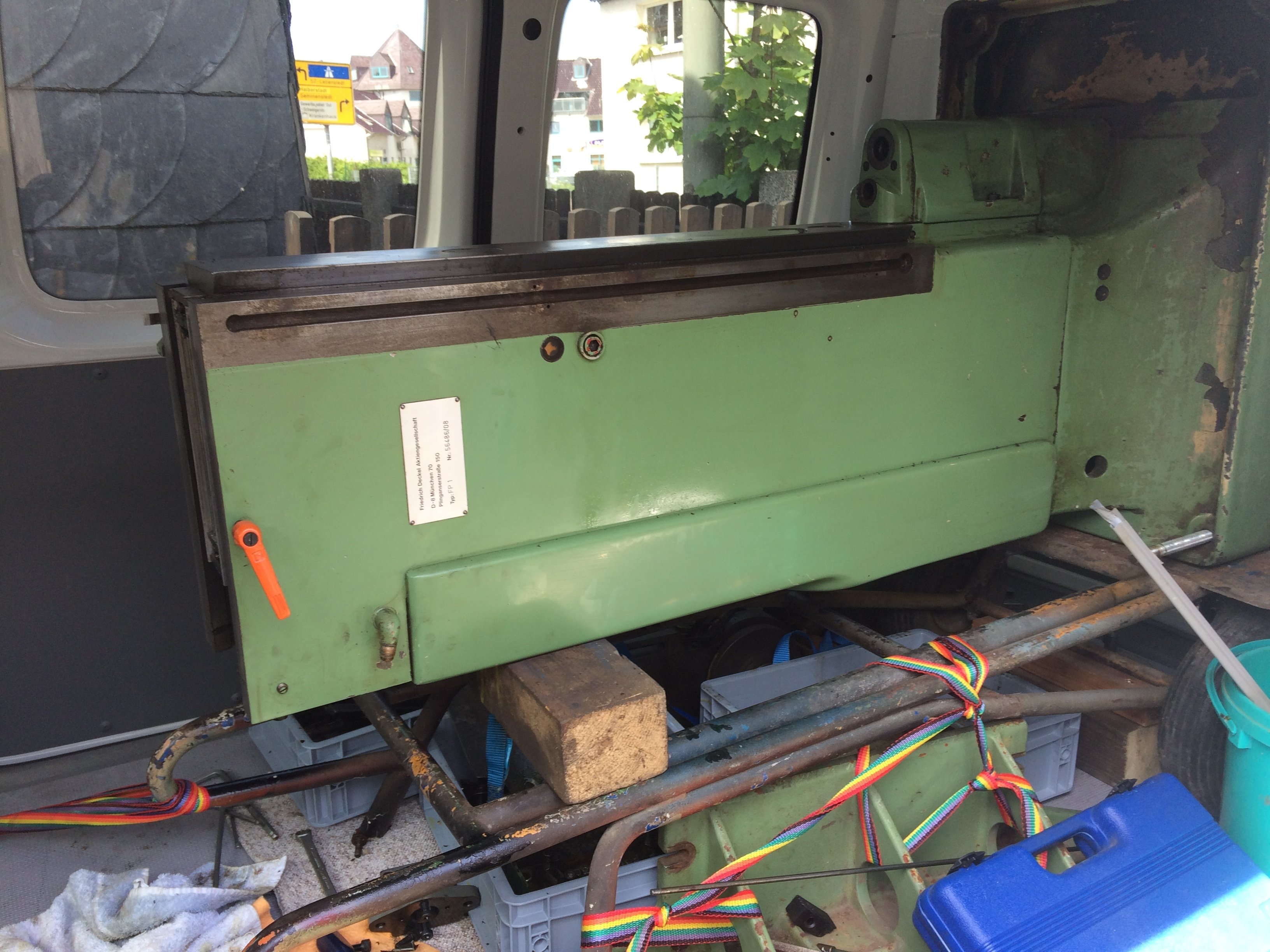
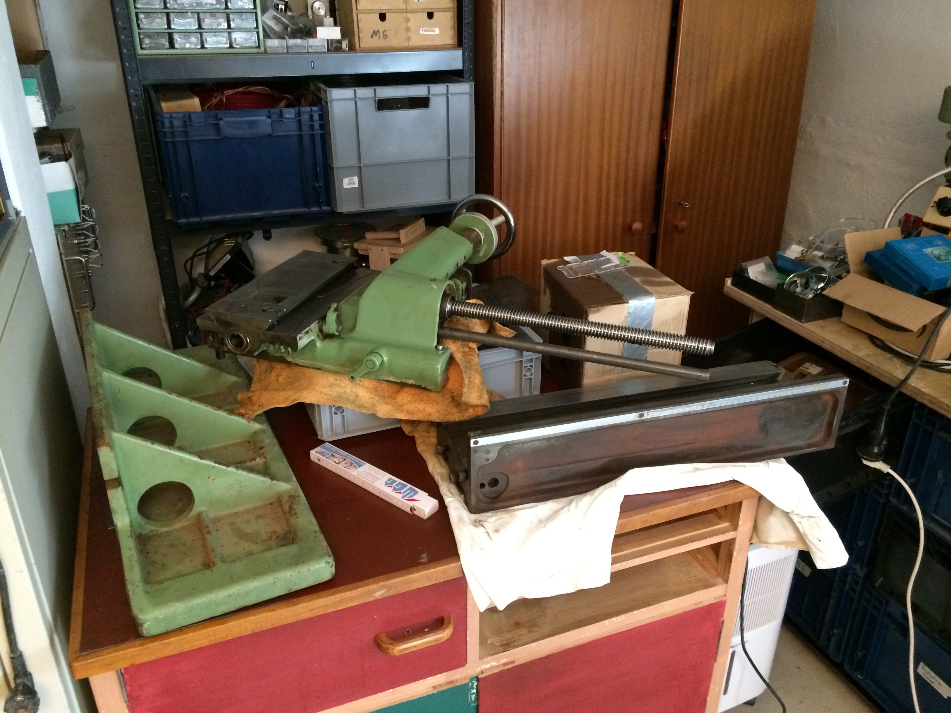
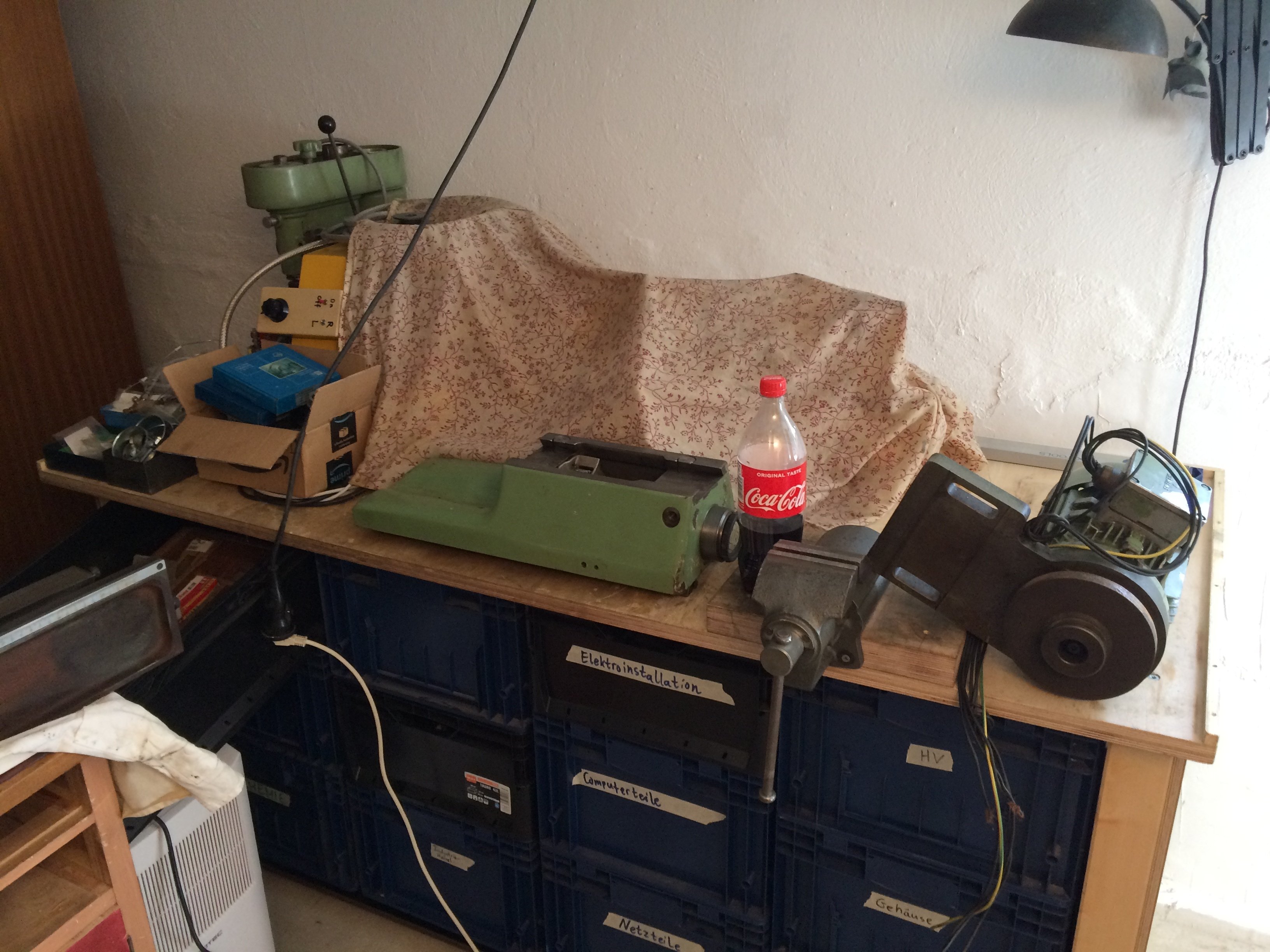
In early May 2020, towards the end of the first wave of Covid-19, this machine appeared on eBay Kleinanzeigen for about 24 hours:
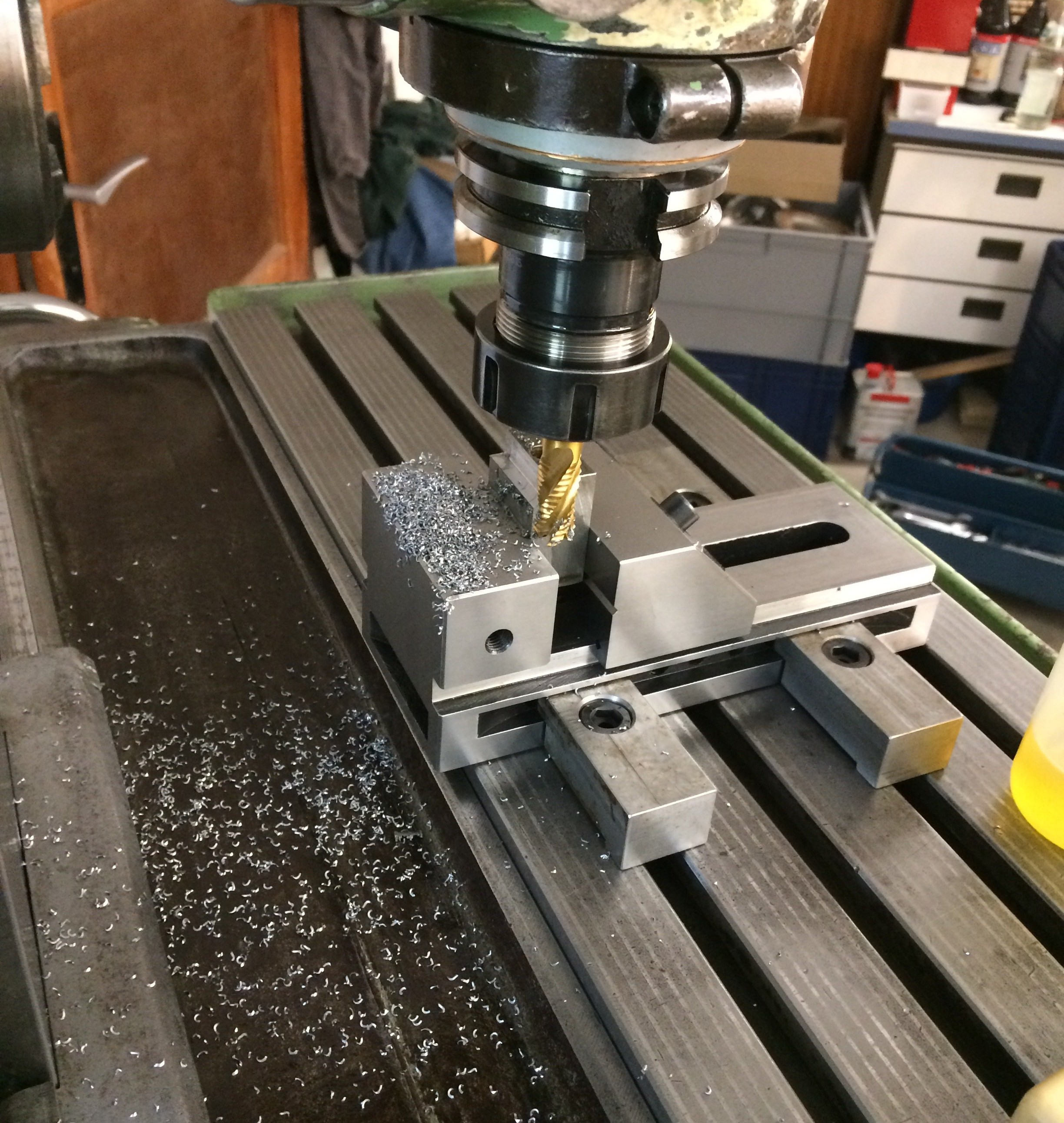
This article is about how I dismantled this machine piece by piece, cleaned it, and put it back together. Today – after a good year – chips finally flew again for the first time:
It all started when I had my small lathe up and running back then, and the wish for a milling machine grew bigger and bigger. Various online listings on eBay, eBay Kleinanzeigen, alibaba.com, etc. were inspected, but for my applications (e.g. vacuum flanges) an FP1 increasingly seemed the right tool. When I then got to do a test cut on a Franz-Singer-overhauled FP1 at TU Braunschweig (many thanks again here!), it was over for me.
Seek and ye shall find. #
Of course affordable offers are few and far between, so it was clear that without a saved search nothing would happen. That search would naturally trigger every hour or so, because sellers also know how desirable a “Deckel FP1” is ;-) After several other offers – some quite tempting – at 3 a.m. between Saturday and Sunday in Hannover, the machine shown above appeared. It fit my hunting profile perfectly: vertical head present with SK40, dial wheels for the gear selectors, no electrical cabinet included -> electrical fiddling required (i.e. a limited buyer pool) and no hours-long drive to pick it up. At the time I was staying with my parents in Wolfenbuettel, so a pickup in Hannover meant a convenient one-hour drive each way.
A direct message at 3:05 a.m. saying I’d like to buy the machine (after a viewing as soon as possible) went unanswered, however. The next day a phone call to the seller cleared things up: I really had been the first interested party with my nocturnal message, and (around 10 a.m. on Sunday) he had already been so swamped with messages it was almost too much for him… All the better, then, that I could line up a viewing-and-possible-pickup appointment for one of the following days. My long-time good friend Hartmut had time on short notice, and another good friend named Felix lent me his VW Caddy (which I would later even buy from him, but that was not yet clear at the time), so nothing was in the way of the tour de force.
Equipped with a fairly hefty hand truck and a good amount of (measuring) tools, off we went. On site we got to do a quick test run, which – given the missing electrical cabinet – could only be done by jamming the bare wire ends directly into the CEE socket of a three-phase extension cable. You shouldn’t do this of course, but I had stupidly not thought to bring a CEE plug, and one wasn’t to be found on the spot either. The machine ran reasonably smoothly and the gears could be shifted (at standstill) without any binding. The feed wasn’t working, but this could be traced back to a sheared shear pin (and there was a reason for that – see below). Furthermore, the feed “joystick” was missing, but in the following weeks I was able to source one (from a different machine) via eBay Kleinanzeigen.
First inspection #
A particularly critical point when buying an FP1 is the spindle bearings, as anyone interested will know. On this year of build they are needle bearings running directly on the spindle sleeve and the spindle itself. At the time that was certainly state-of-the-art (and possibly even emerged from it), but today, in the event of a defect, these spindles can mean the economic write-off of the machine. Clearance is set by selecting needle diameters so that they fill the gap between spindle and sleeve with about 3..5 um of play. Manufacturing variation means the absolute needle diameter required varies a bit from machine to machine. If the needles are worn or the running surfaces have to be re-ground, you need matching needles in um-stepped diameters. These are (as far as I know – corrections welcome!) no longer available or only as remaining stock for this style of bearing.
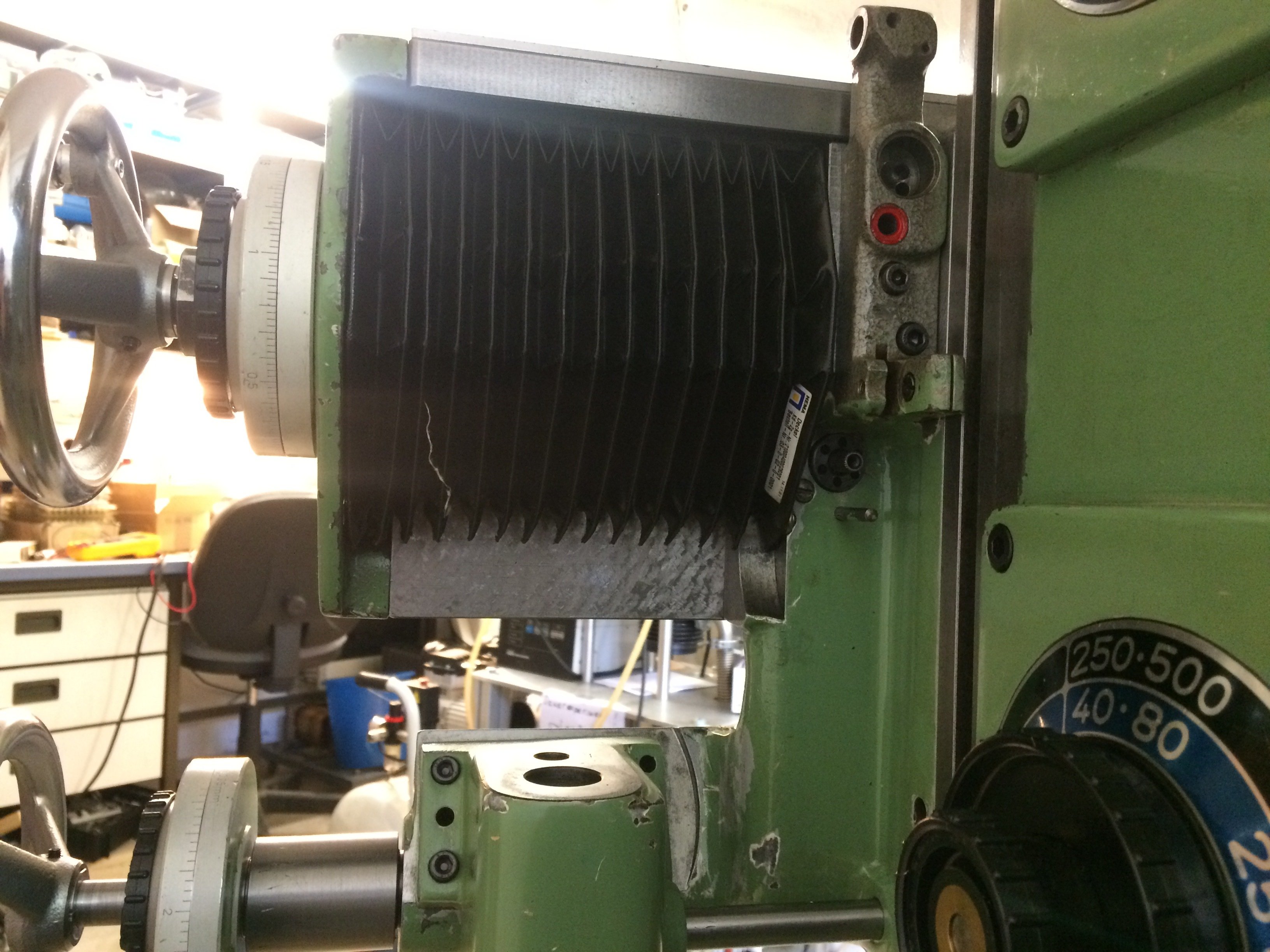
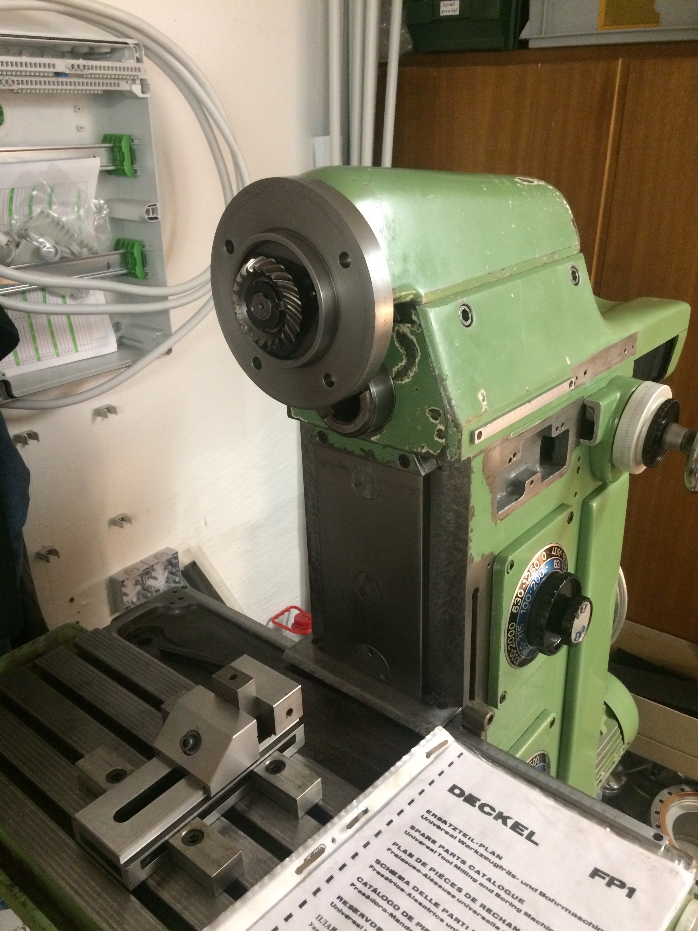
The quill housing of the vertical head was therefore taken off and the spindle turned by hand. Bingo: several detents could be felt, and the inside was rather grimy:
A wise person might have sighed at this point and gone home. I had had a look at eBay etc. beforehand and found an offer from Franz Singer for a quill overhaul at around EUR600-800. You should bear in mind, though, the qualifier “Prerequisite: needle running surfaces must show no damage.”… Another point is that several people had reported broken ball bearings for the bevel gear at the top of the quill housing. Under time pressure I had not removed the quill itself from the housing (and I would have felt the detents anyway, see below) – only turned the whole assembly by hand.
Anyway, the rest of the basis of the machine (ways, gearboxes, general impression) seemed good enough to me to take the residual risk regarding the vertical head. The bare offered machine cost me EUR2,000 in the end and roughly 3 to 6 months of searching.
Transport #
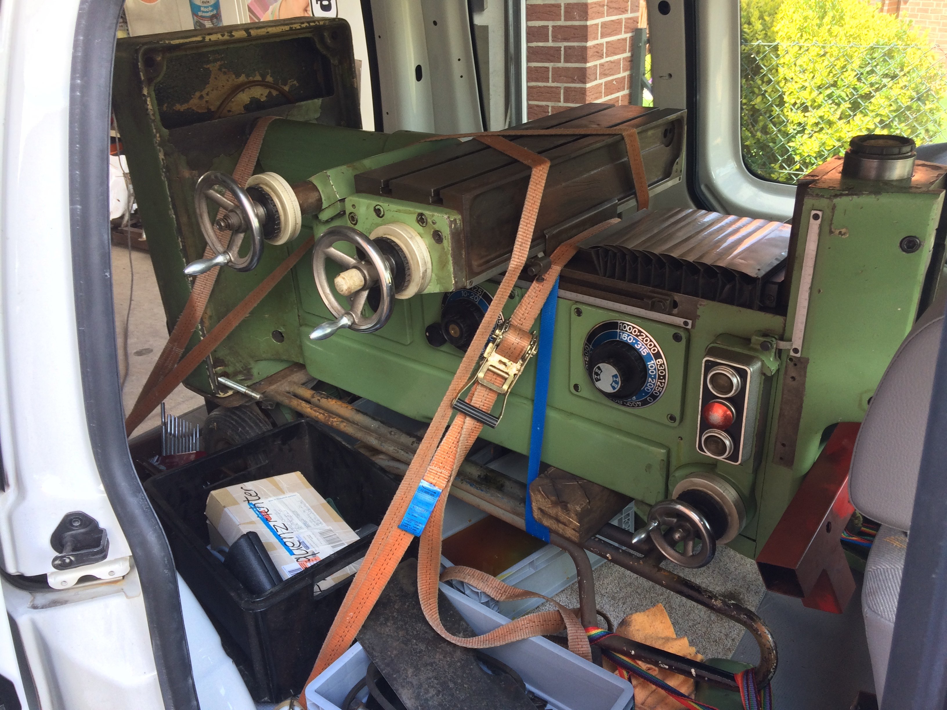
The next question, of course, was how to get the prize home. With the combined forces of the seller, his two sons, Hartmut and me, we just managed to stand the machine up on its back on the hand truck and then tip it head-first into the car. Two loading ramps under the wheels of the hand truck then helped to heave the foot of the FP1 inside as well. A surprising amount fits into a Caddy, but the FP1 lowered the suspension pretty thoroughly. For the record, the orange ratchet strap during loading kept the FP1 secured to the hand truck.
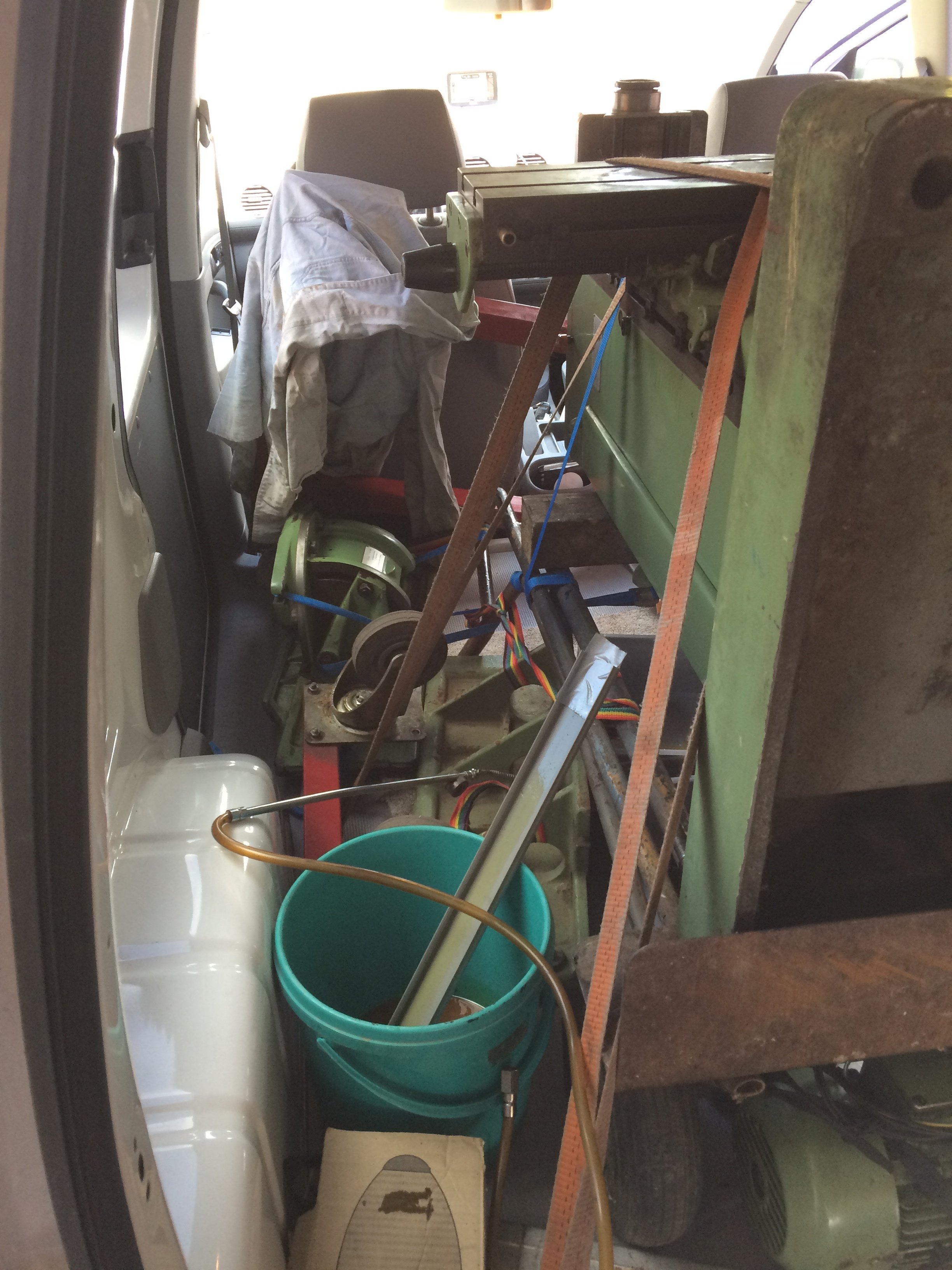
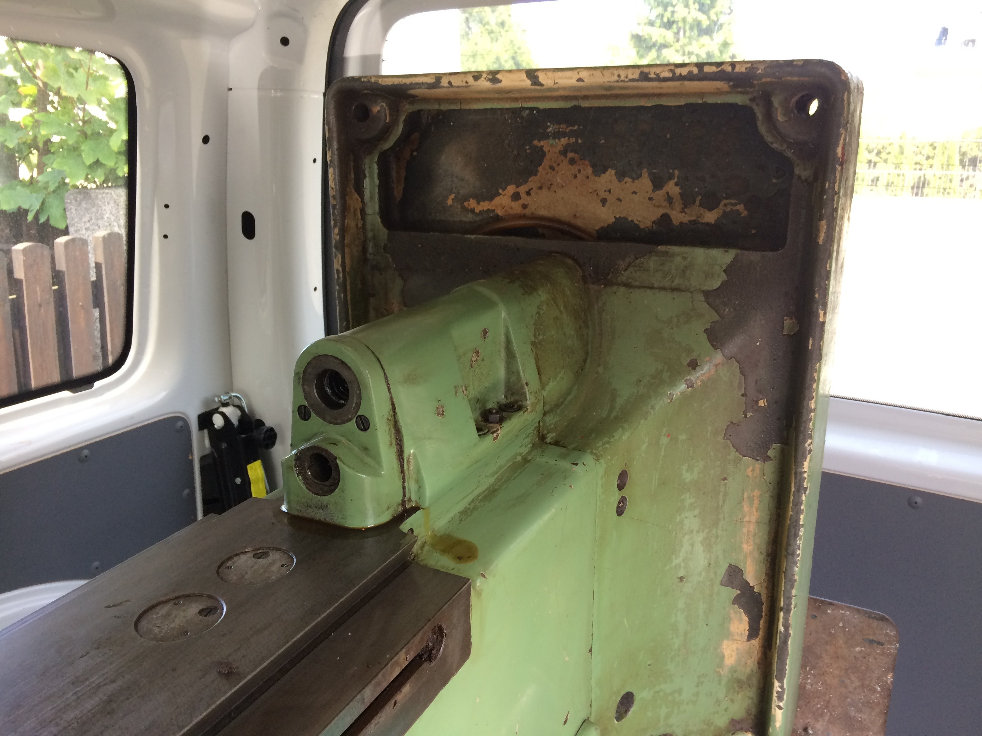
Naturally, all the remaining oil residues started seeping onto the loading area as soon as the mill made itself comfortable. A spare Euro-box quickly slid underneath was able, however, to forestall greater catastrophes. For the record: of course the existing oil drain points had been opened beforehand to drain the oil…
First inspection at home #
Once at home I tackled the vertical head first, to find out whether, for the rest of the year, I’d be able to afford anything other than noodle soup, or whether by some miracle the needle bearings were still OK.
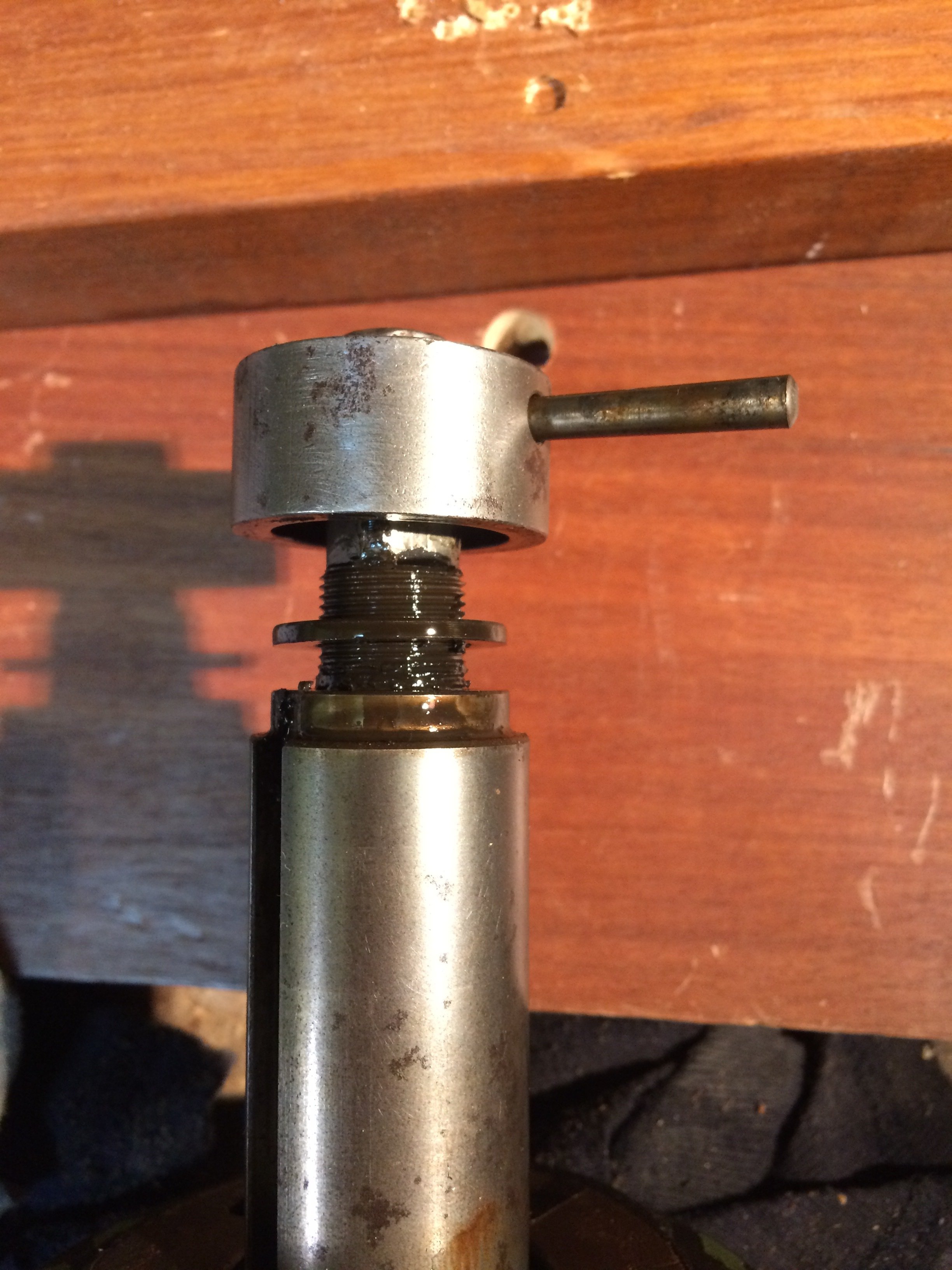
First, the locking pin for the cap on the drawbar was driven out:
The pinion shaft for the quill drilling feed comes out next:
And just like that, you have the quill itself in your hand:
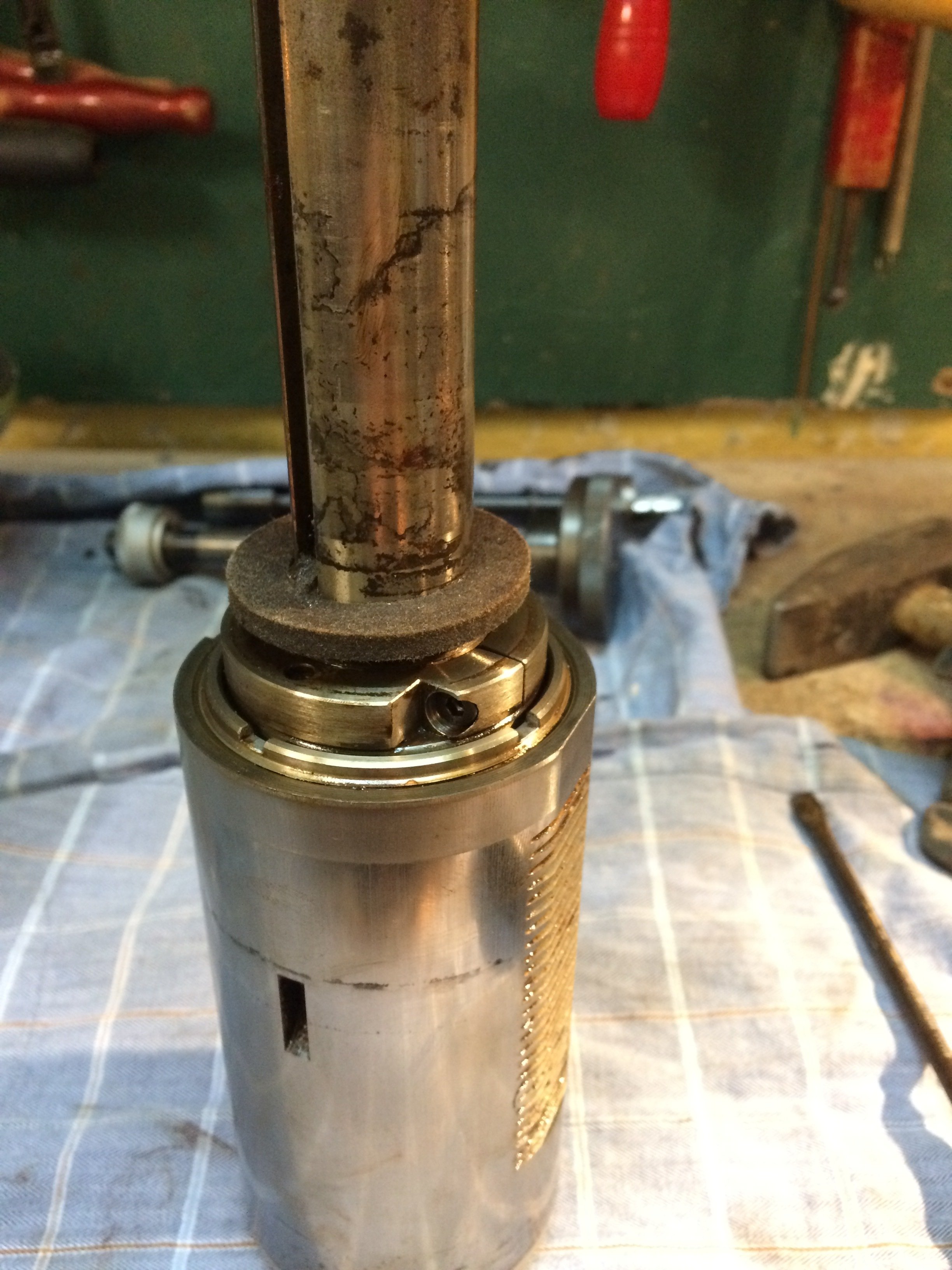
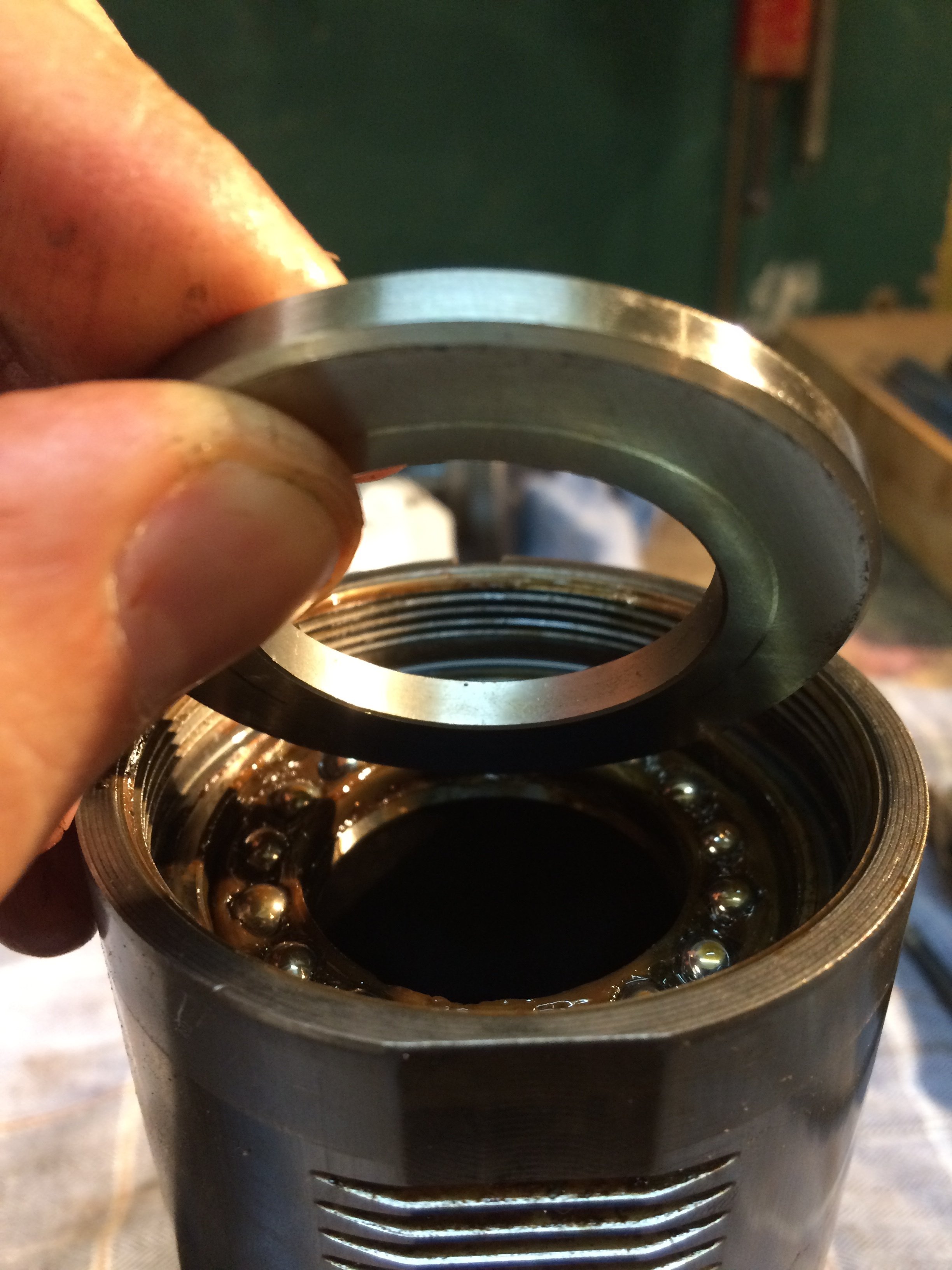
The clamped nut can be unscrewed and you reach the thrust bearing:
The whole brown gunk doesn’t bode well, but: “eyes open, soldier on”:
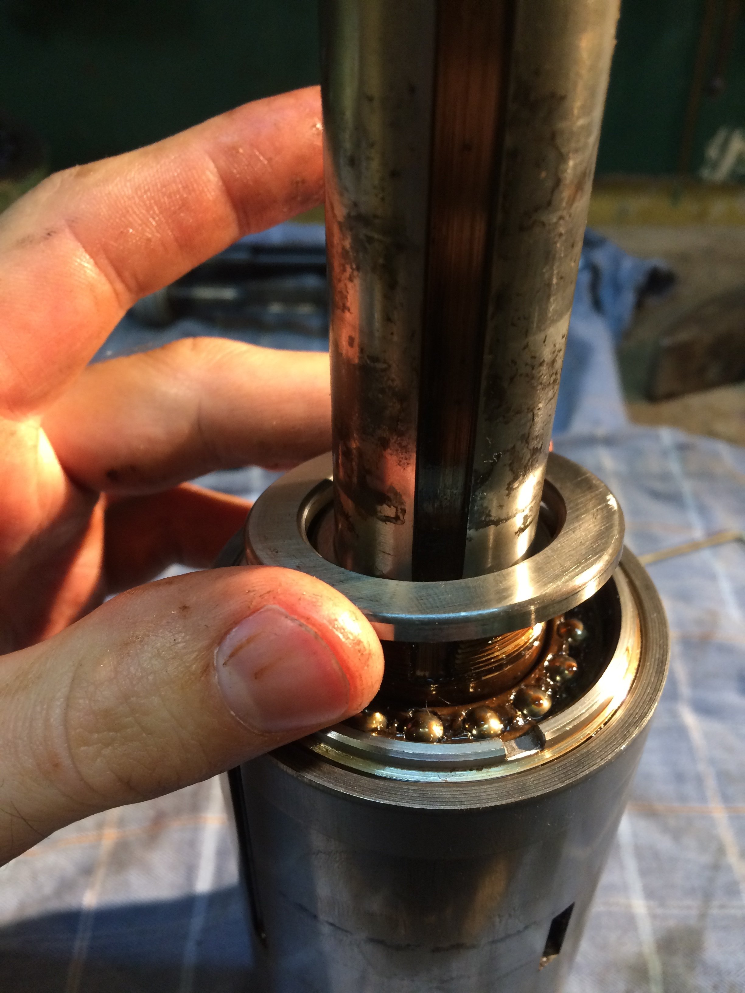
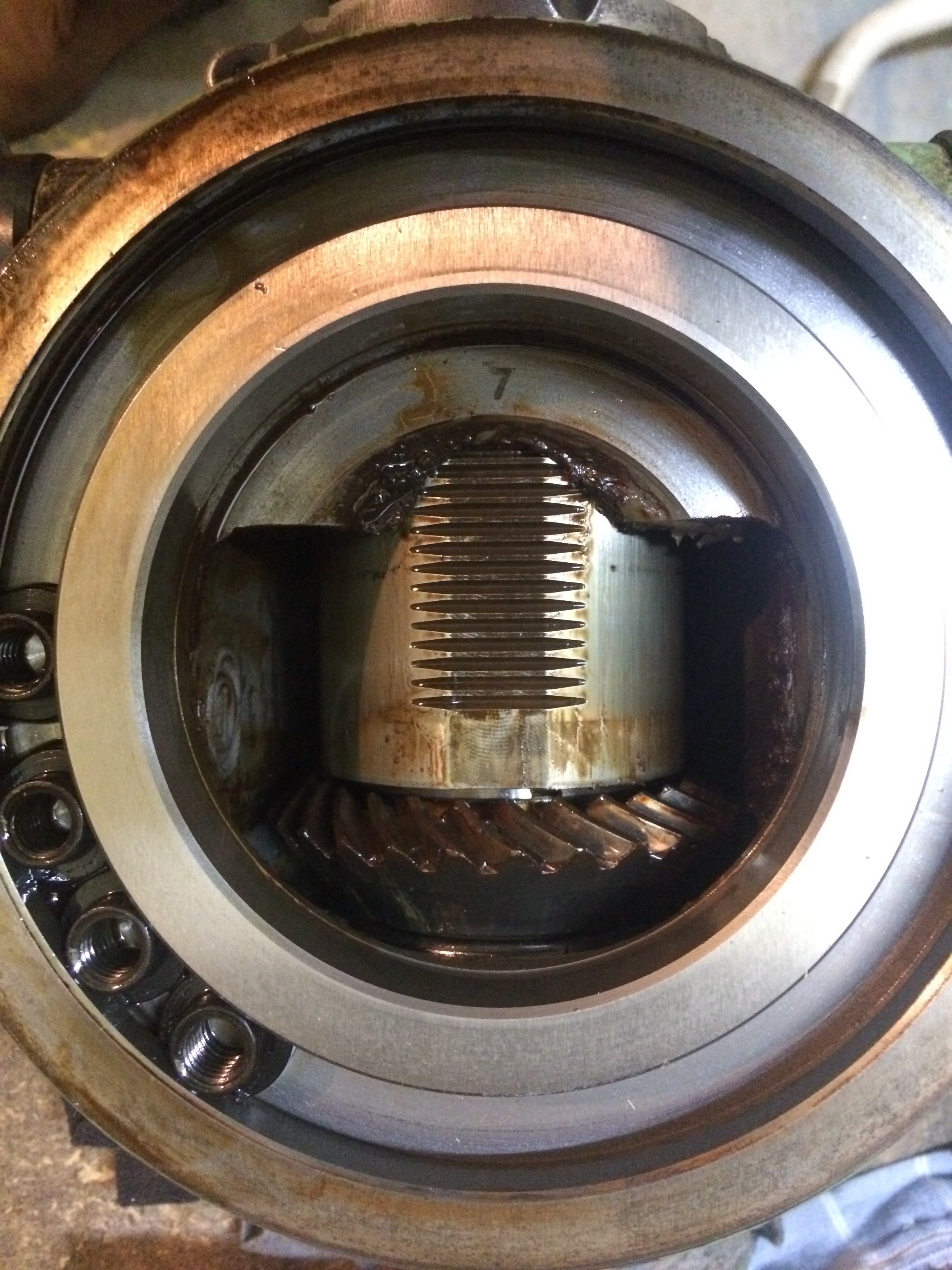
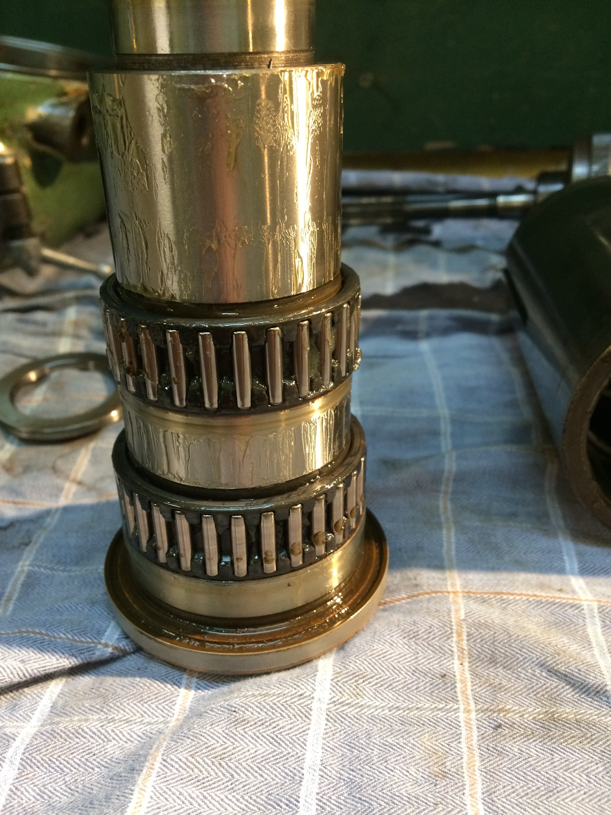
Lucky!!! The needle bearings are still clean and look very unworn:
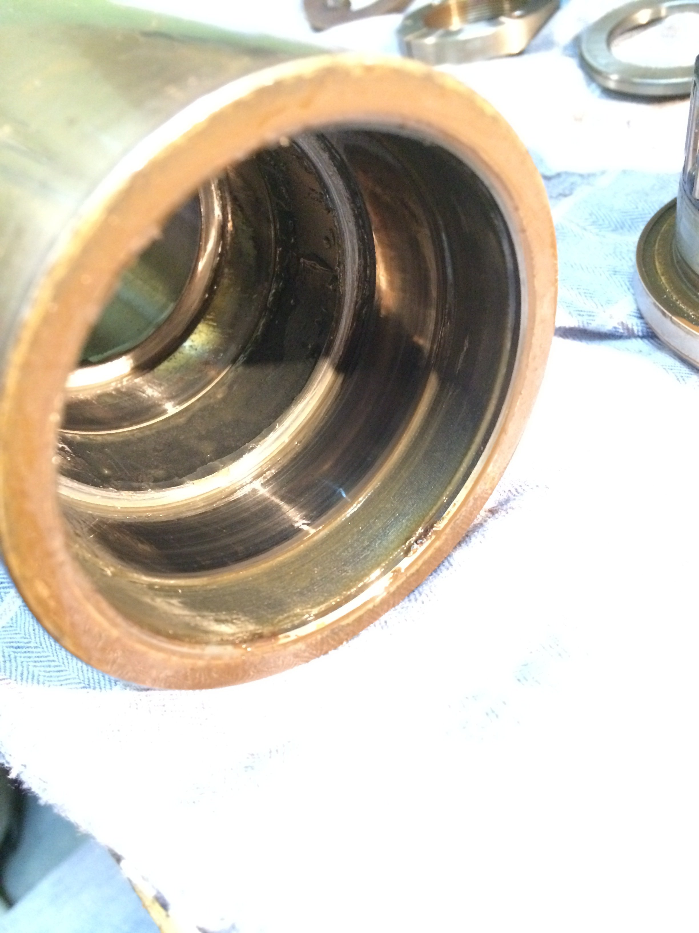
The running surfaces in the quill itself also still look reasonably OK:
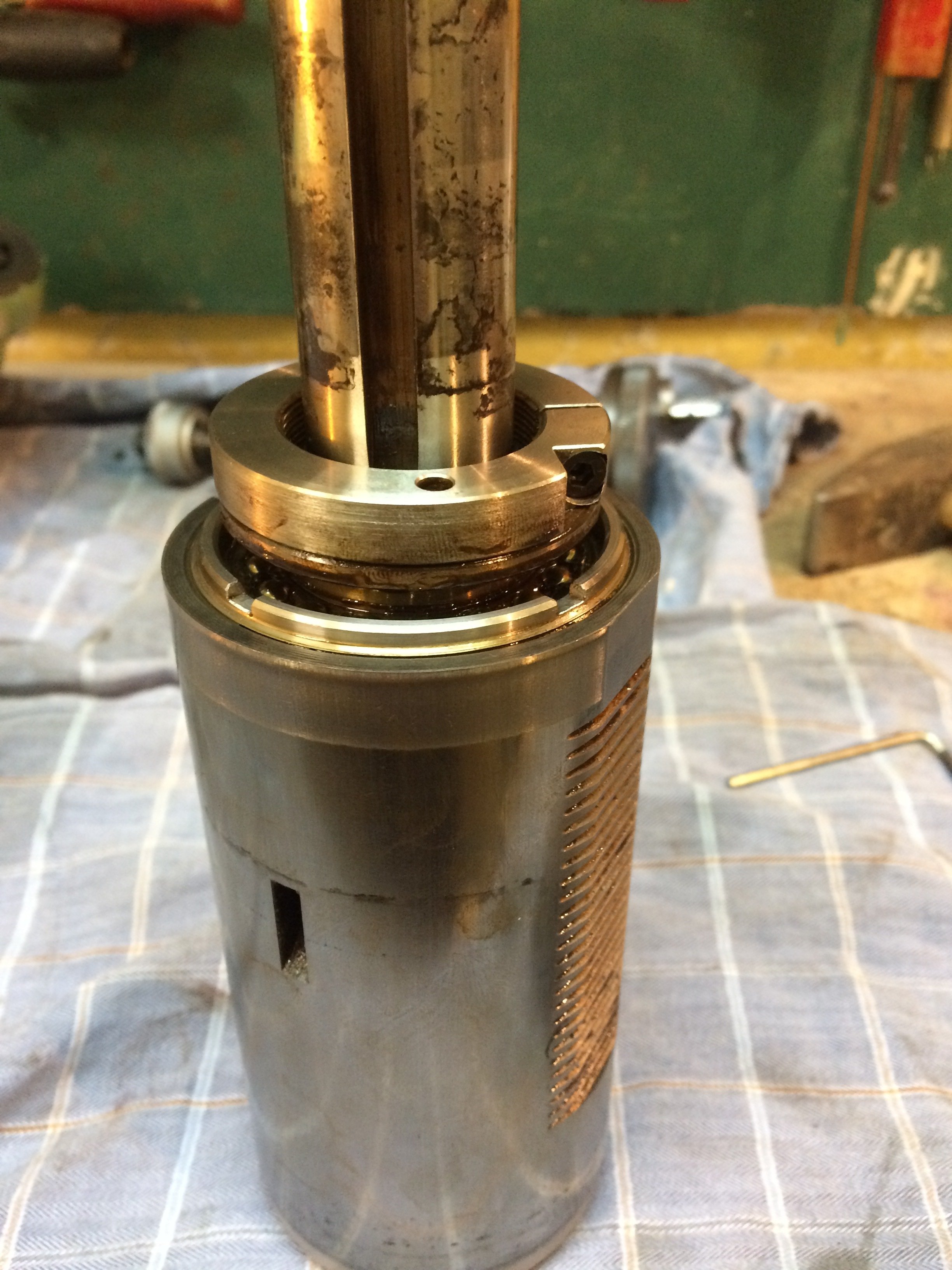
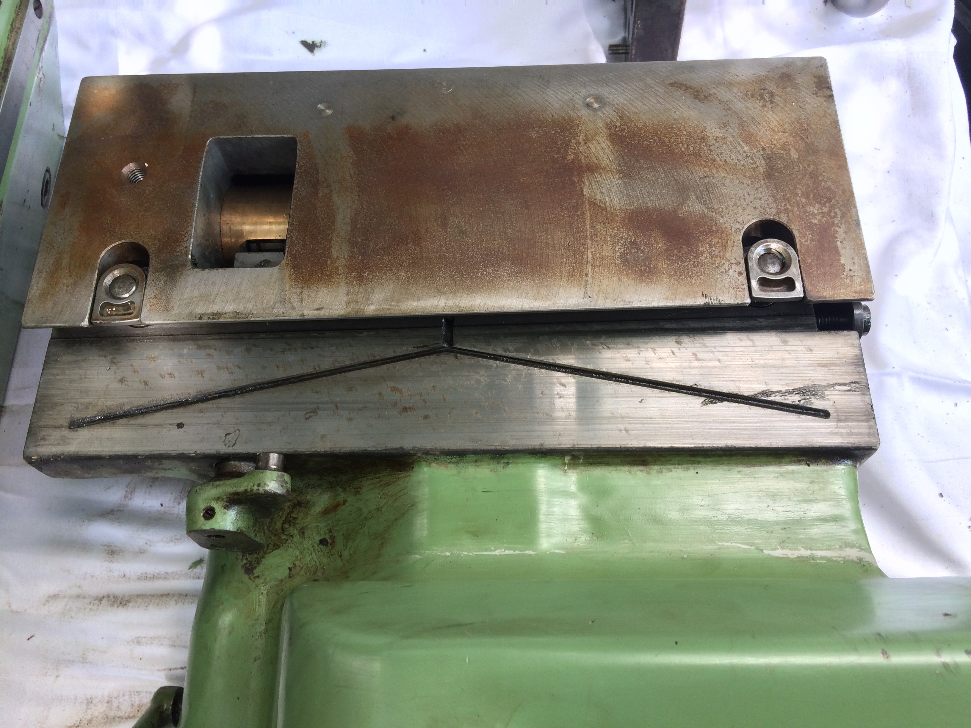
The cause of the quill’s detents was found in the thrust bearing:
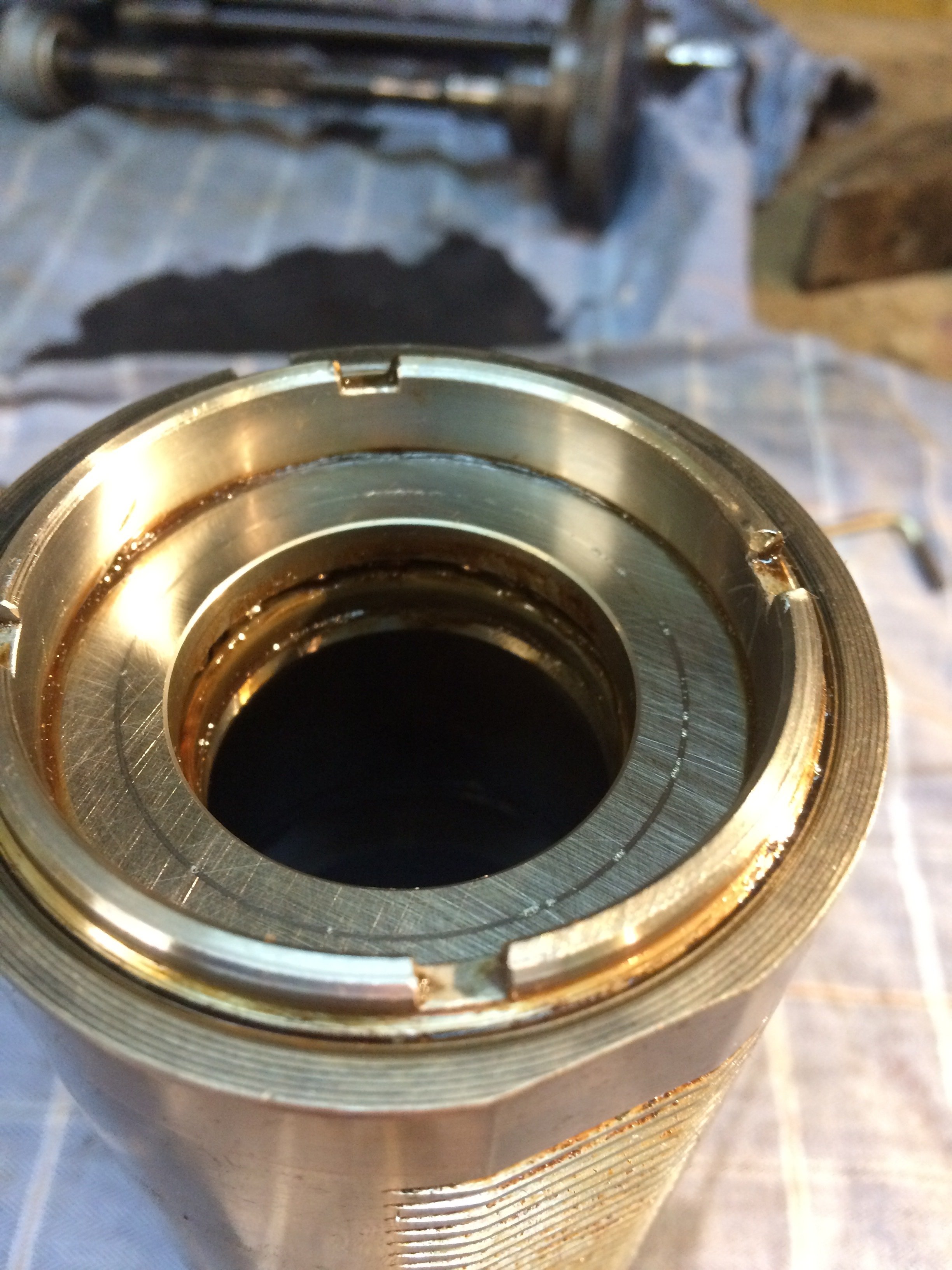
The thrust bearing consists of two thrust ball bearings that run on one side in the supplied “race washers” and on the other side on a disc anchored in the quill. There the race is missing, which under normal operating conditions and loads of an FP1 apparently works satisfactorily. The disc is held in the quill by a four-slot nut:
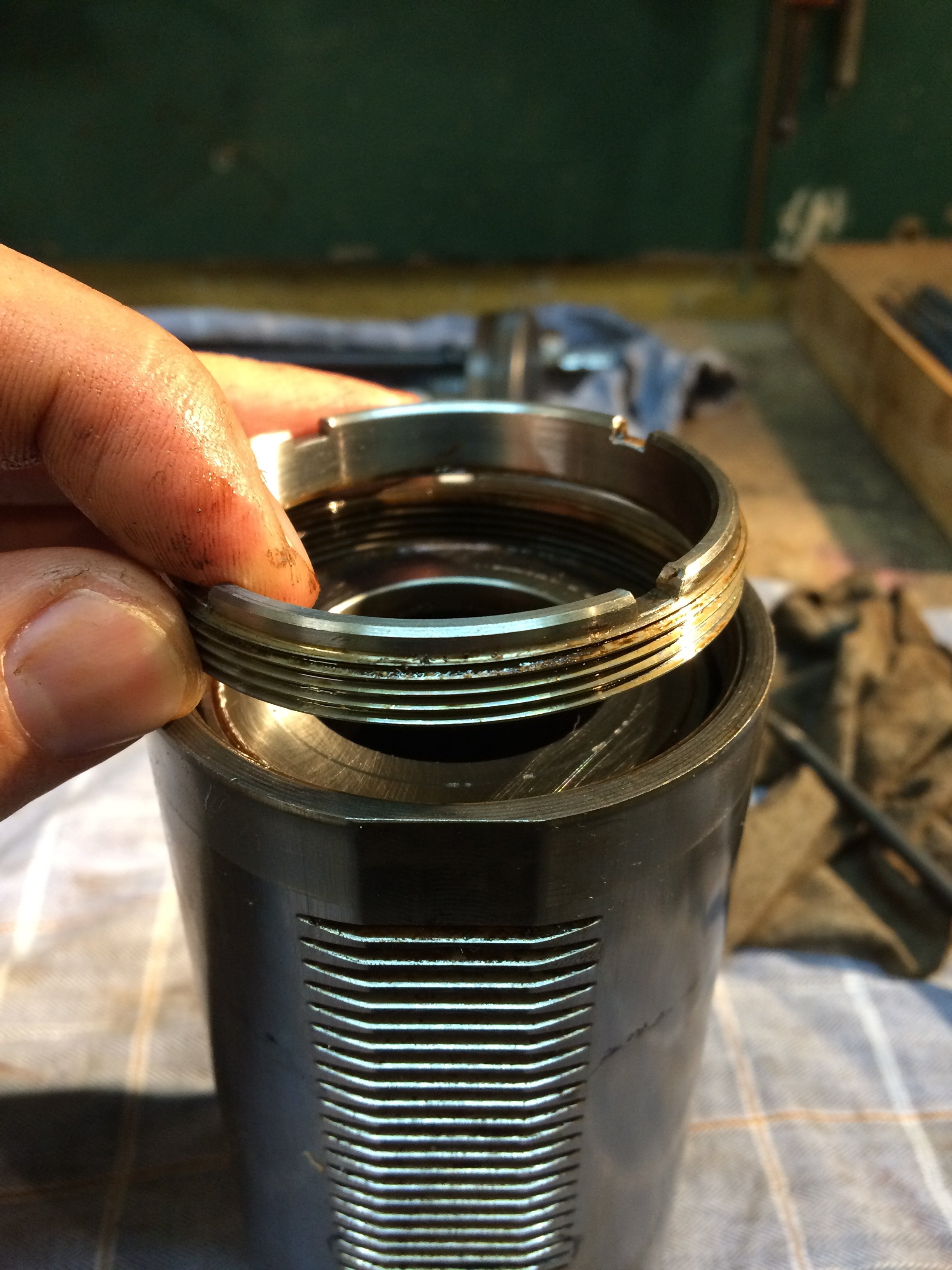
Interestingly, the disastrous wear marks are on the top side of the disc and not on the bottom. When drilling the feed force pushes upward, but a milling cutter is sometimes pulled downward out of the collet. Could this be a consequence of excessive axial force from milling?
When you take the disc out, the lower half of the thrust ball bearing can also be removed:
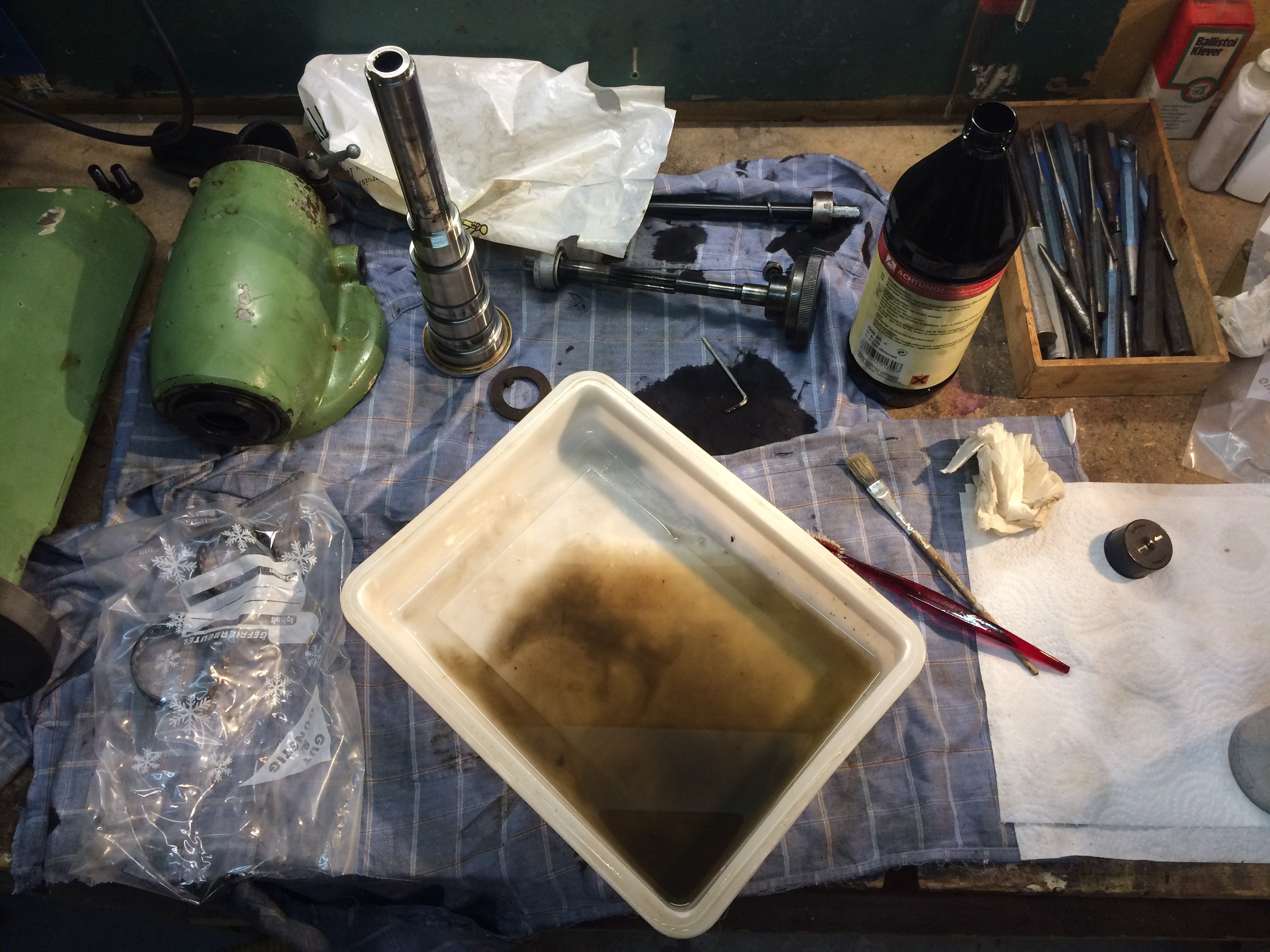
All parts were cleaned in “lamp oil” (kerosene) from the supermarket:
This is a fairly oddly designed affair, which has caused some confusion on the Zerspanungsbude forum at various times: Thread #47254 Eventually Franz (@opa12) shed light on the matter: Post #569220 Franz also showed a successful repair of this defect, in which the “central bearing race” (?) is faced flat and lapped accordingly. Many thanks for this information once again!
This also told me immediately who I would be sending my quill to ;-) A somewhat over-the-top packing job was quickly assembled and after a short phone call and one return shipment by the post (who actually managed to dismantle the parcel), the vertical quill arrived at Franz’s shop, was overhauled and measured there, and ultimately reached me back in Greifswald just as safely.
Franz was able to remove the wear marks in the disc and, on my request, greased the needle bearings with Klueber “ISOFLEX SuperTEL”, as required by Deckel. The measured radial clearance was about 3 um and the axial clearance is now properly set. Since the vertical quill is probably the most critical part of an FP1, it was important to me that this work be done by someone who knows what they’re doing. The overhauled quill now turns wonderfully smoothly, and instils confidence that I’ll be able to do many years of good work with the FP1 :-)
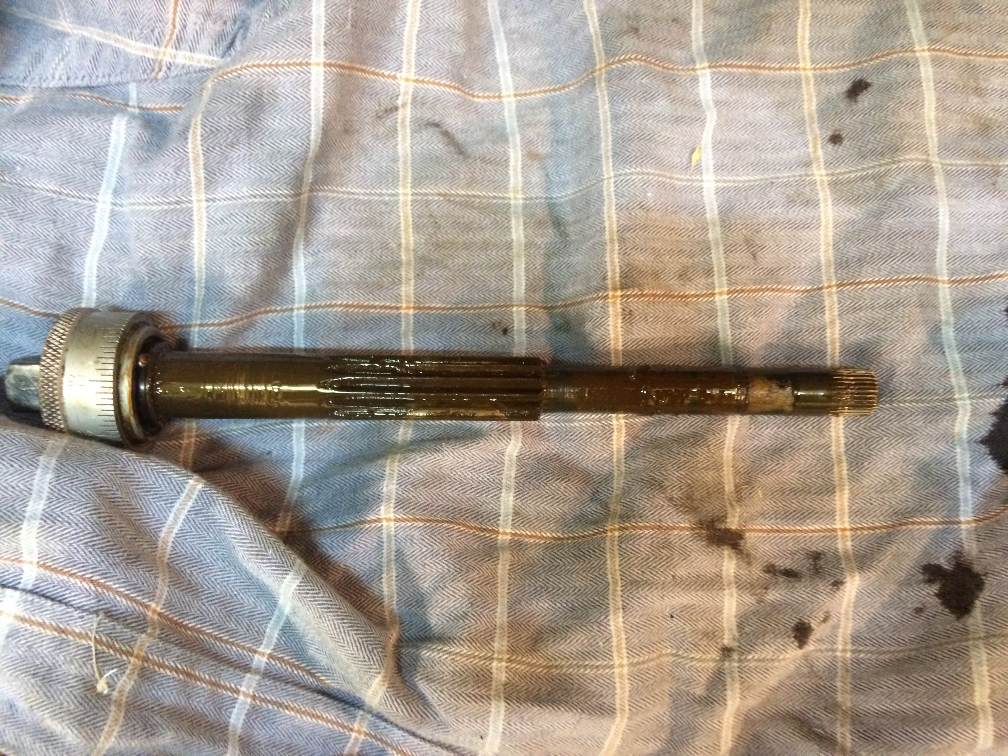
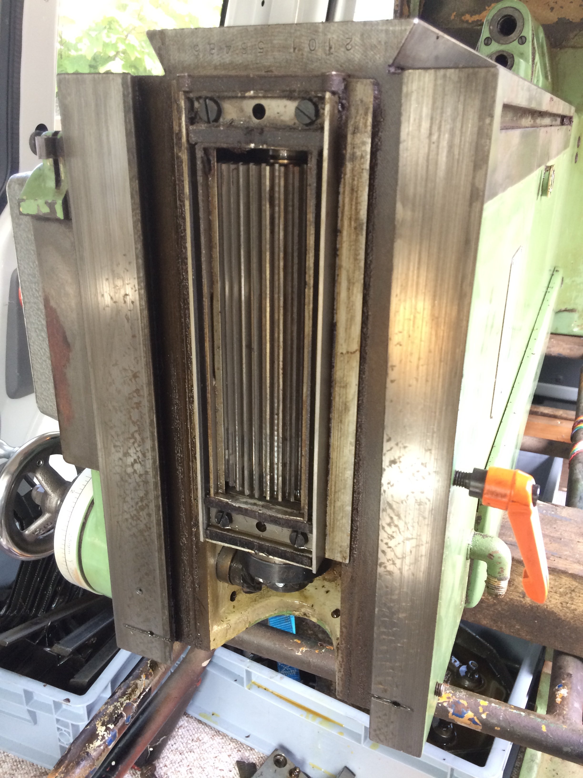
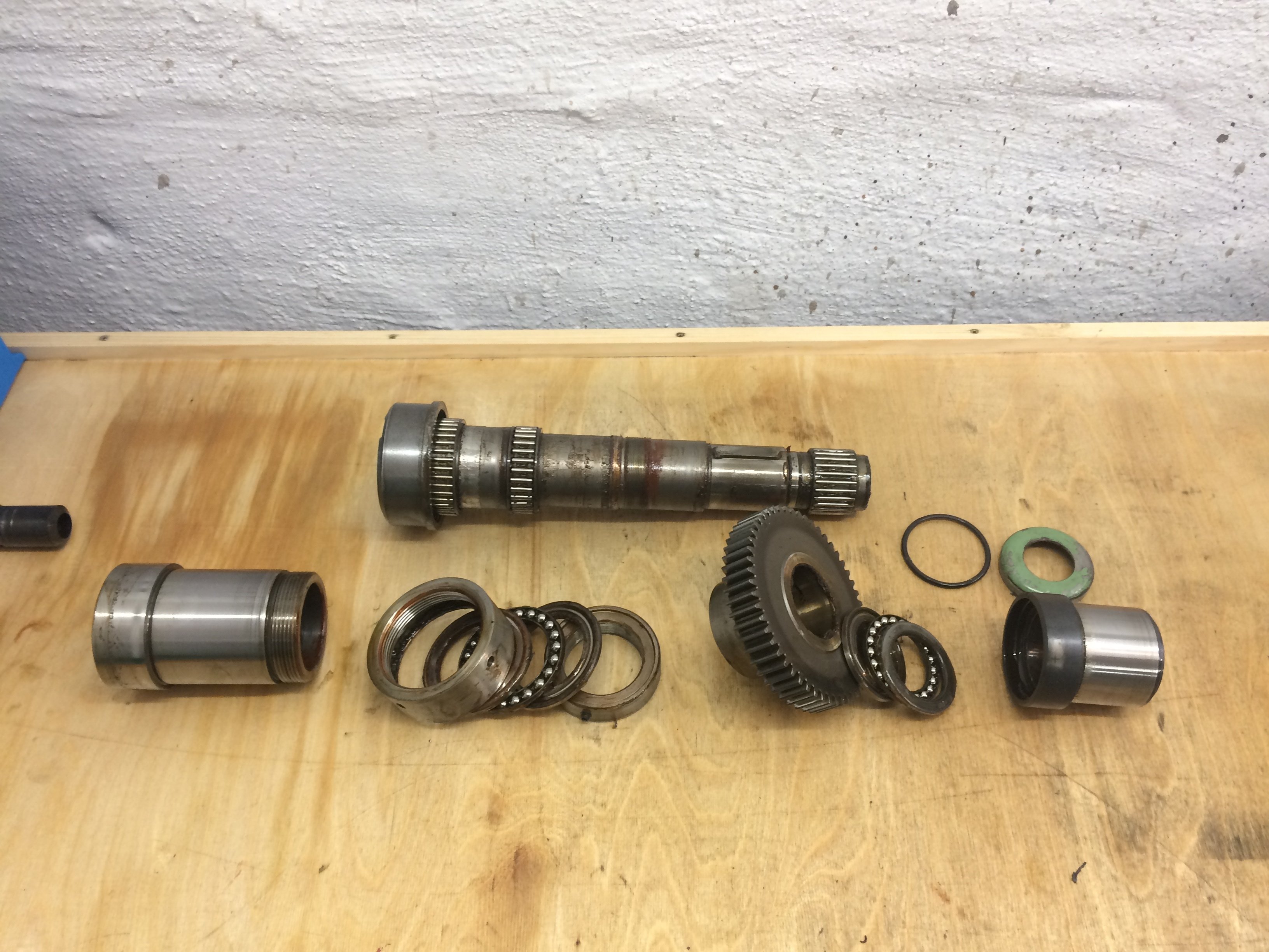
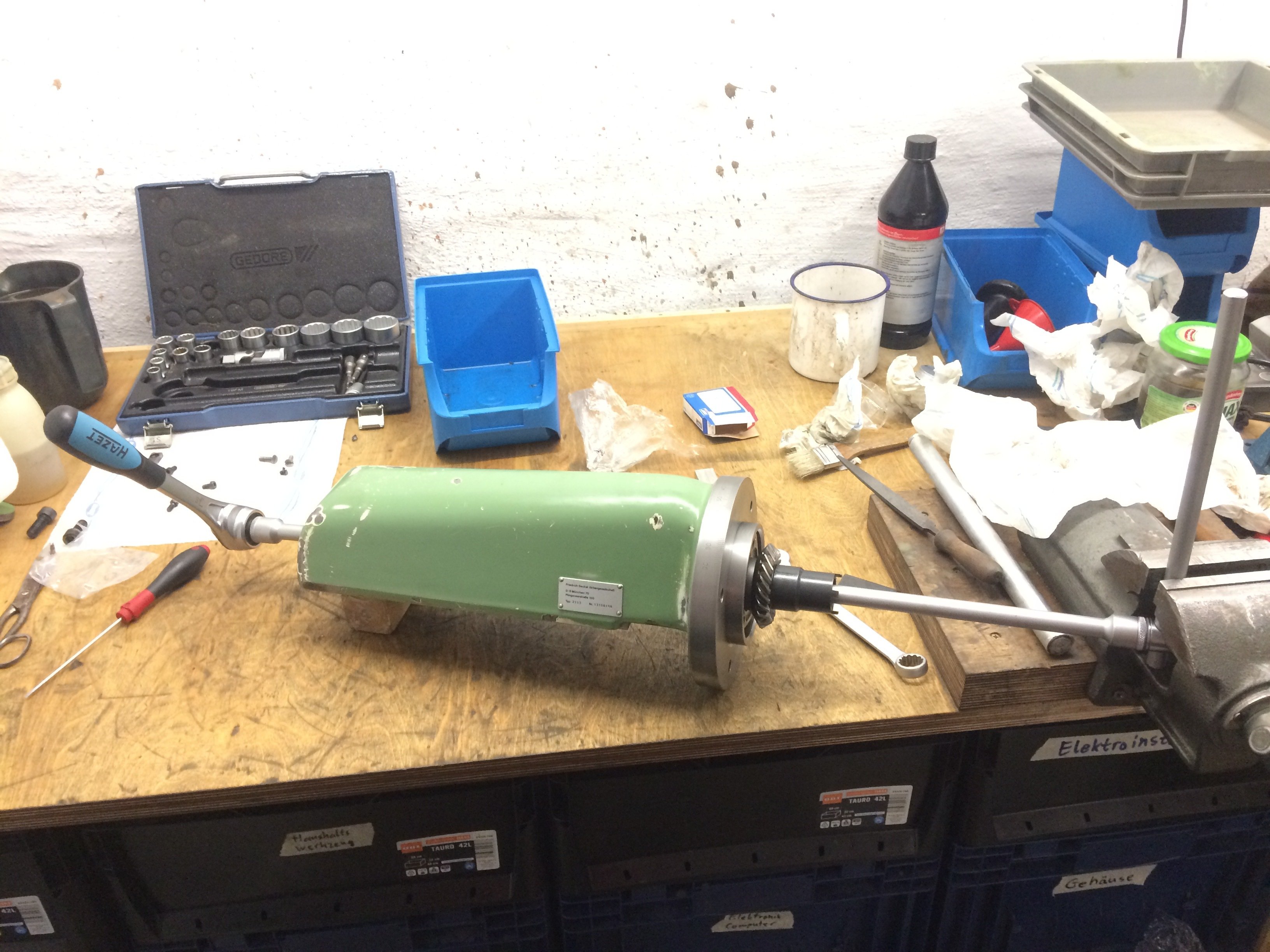
Here is another picture of the assembled innards of the FP1 vertical spindle (taken before the overhaul):
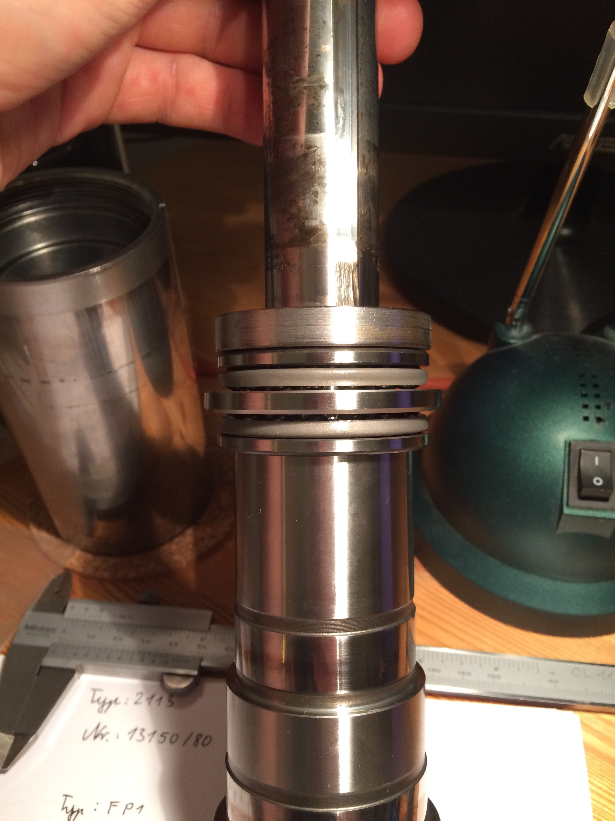
In a fit of madness I had already modelled the individual quill parts in Inventor and tried to design an alternative solution that would fit in the available space but use both race washers of the ball bearings. After Franz, however, assured me that the original arrangement is indeed a series-production design from Deckel and should normally work just fine, I left the original construction in place.
Disassembly #
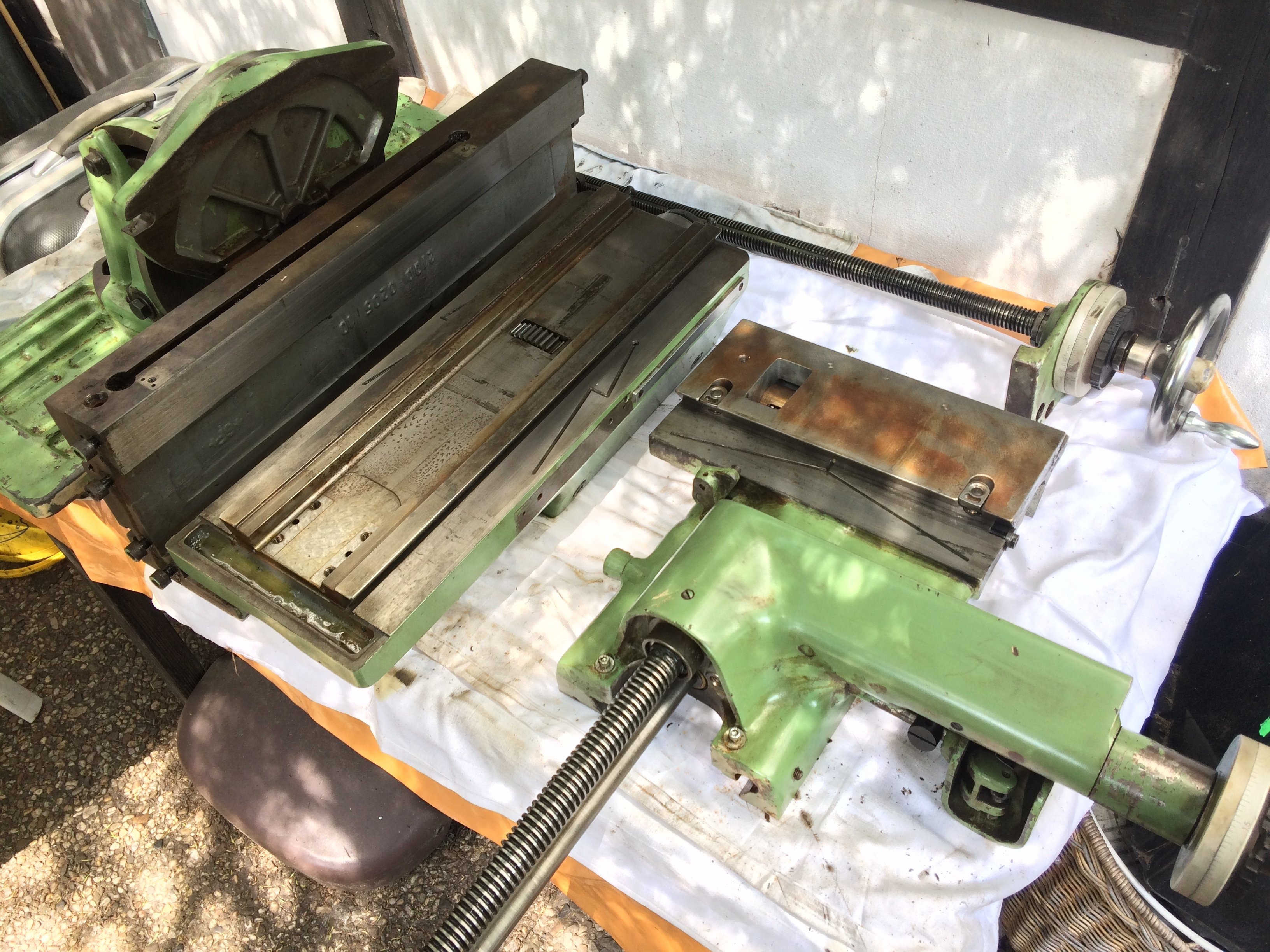
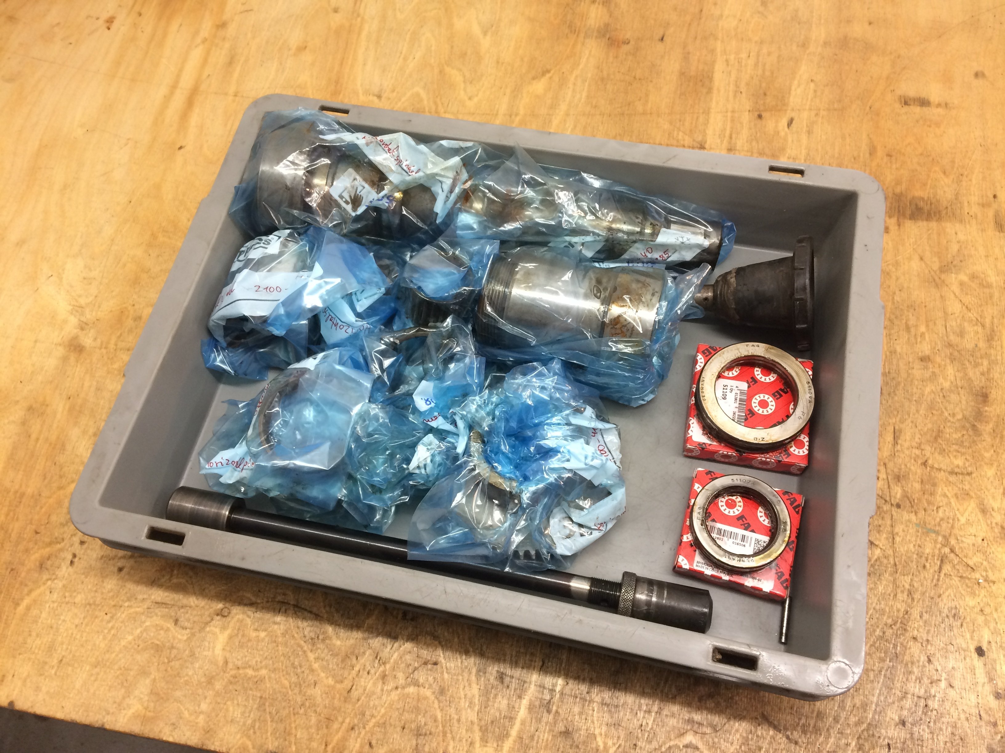
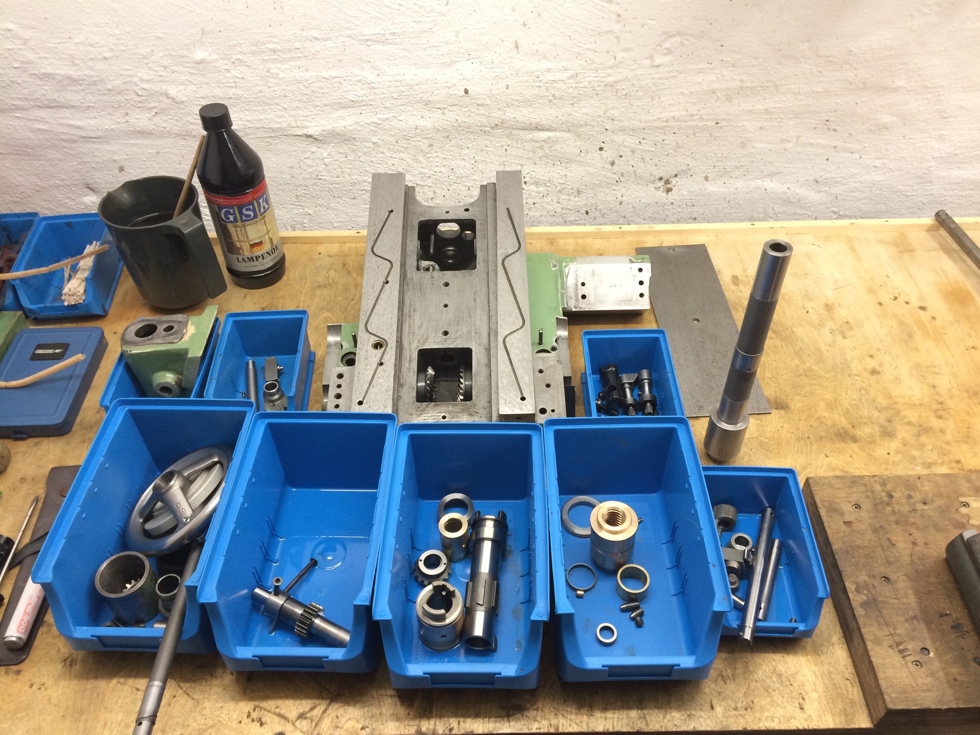
Next on the chronological agenda was further disassembly of the machine. While at the seller’s I could drive right up to the garage, at home I have to go halfway around the house to the basement entrance. Therefore, anything that wasn’t bolted down was unbolted and inspected:
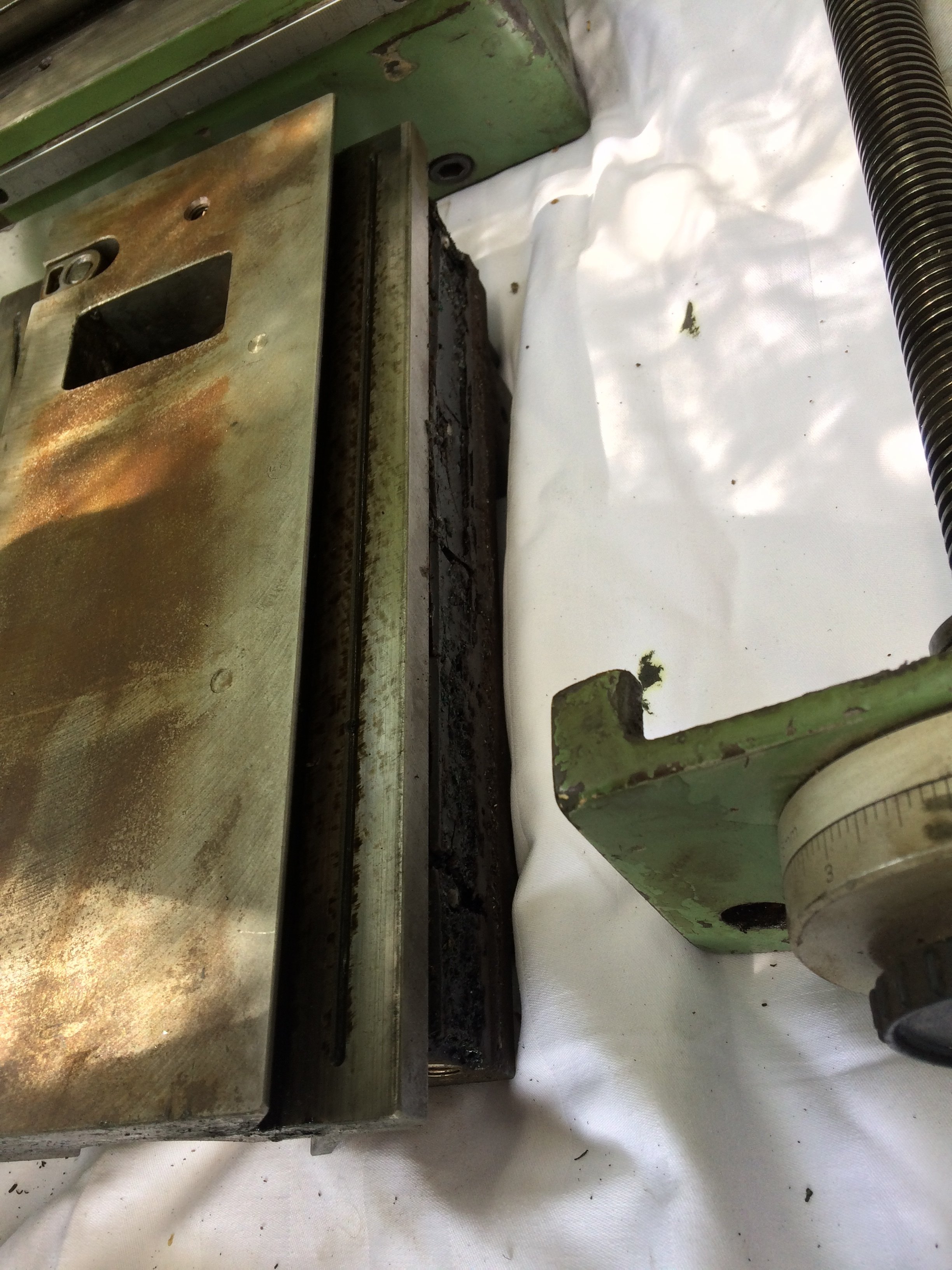
Pleasantly, the way surfaces showed no big galls on this slightly more careful inspection either:
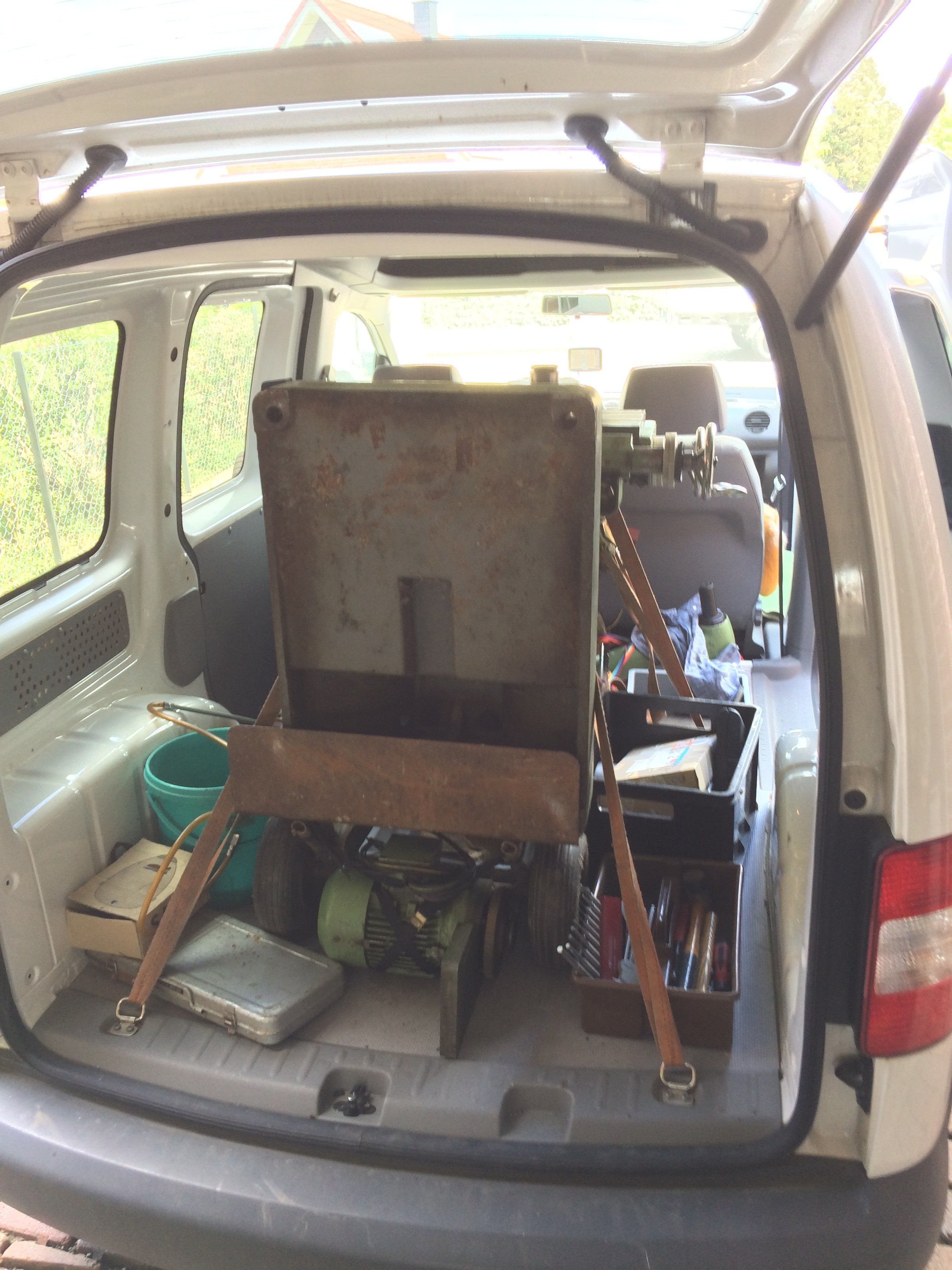
The machine body stayed in the car to avoid having to unload and reload it:
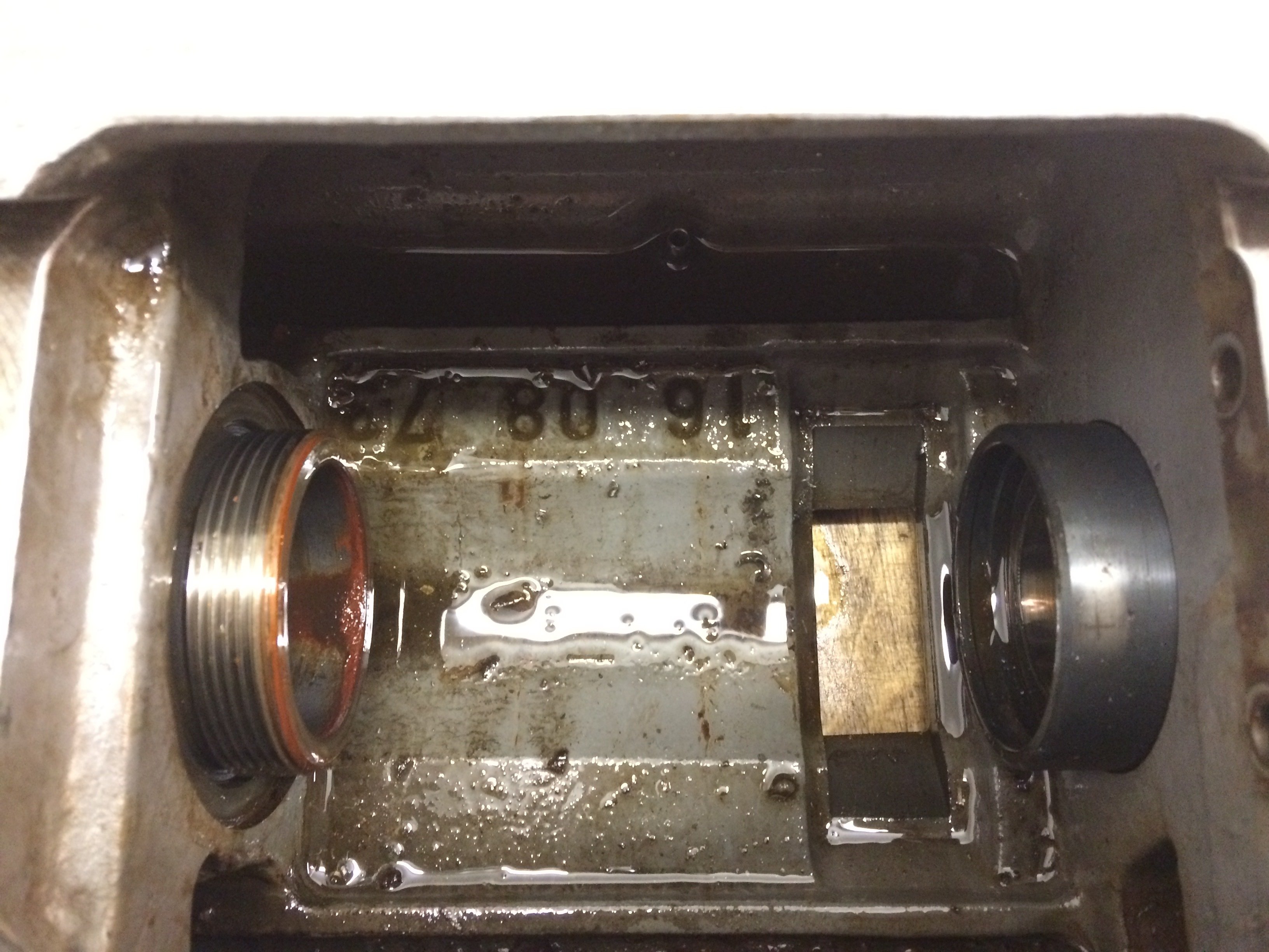
Pleasantly, a previous owner had already done me the unspeakable favour of cleaning the coolant sump:
So prepared, we headed home to Greifswald.
Unloading #
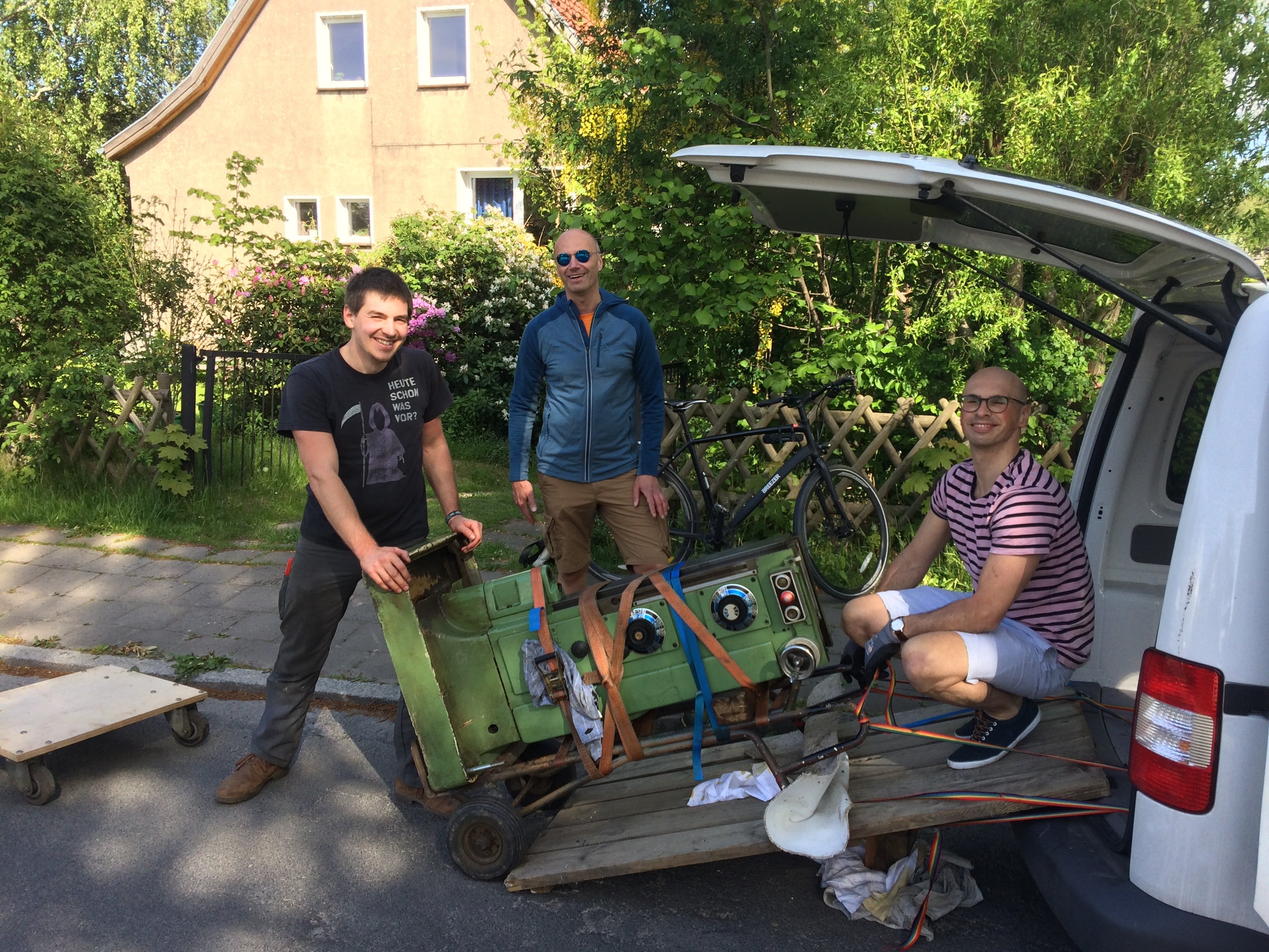
Back home in Greifswald, I lined up three colleagues to help unload the machine. Me on the left, Thomas in the middle, Peter on the right. Hannes took the photo and is therefore unfortunately not in the picture. Heartfelt thanks to all three of you for your helping hands!
Together we managed to manoeuvre the machine body together with the removed parts into my workshop:
All previously cleared horizontal surfaces are entirely covered:
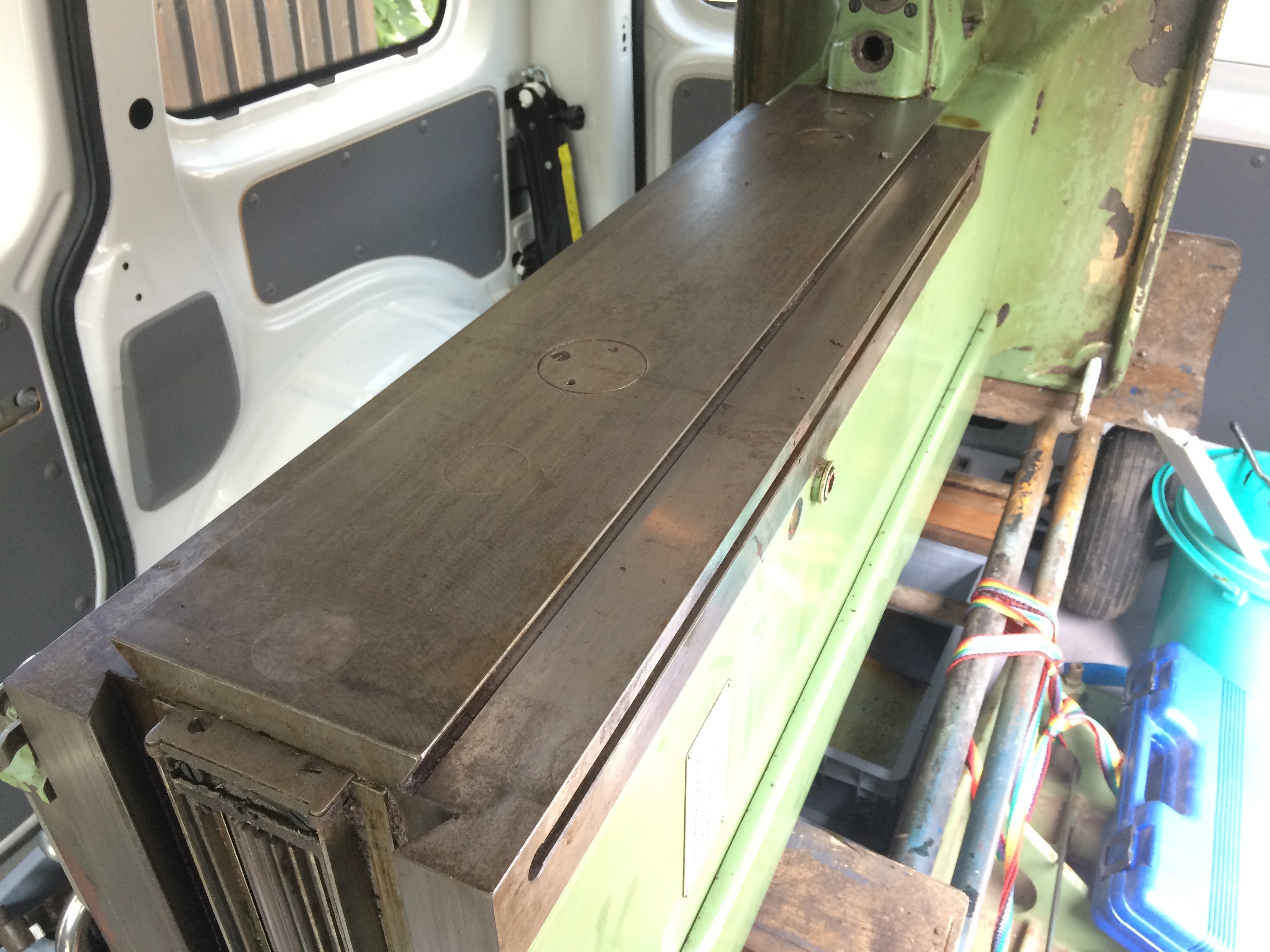
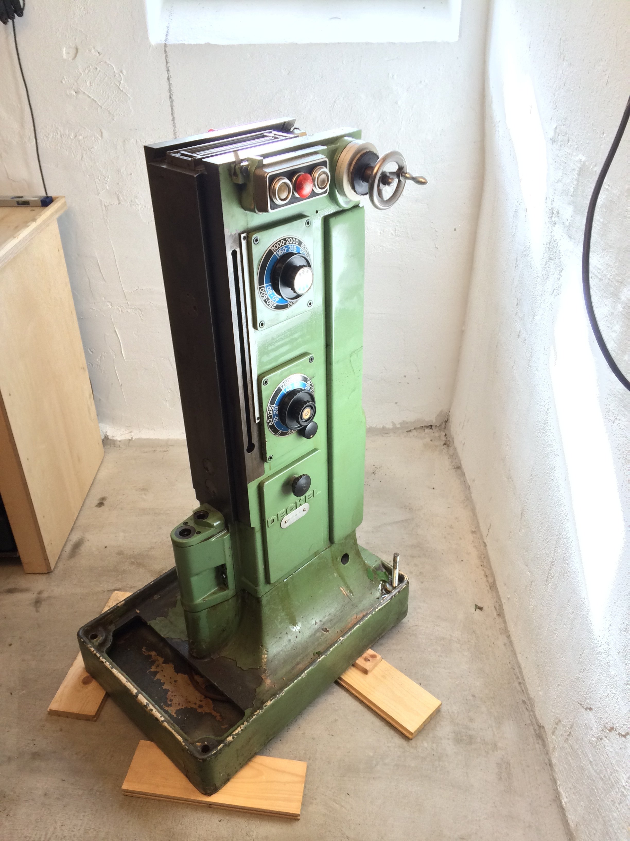
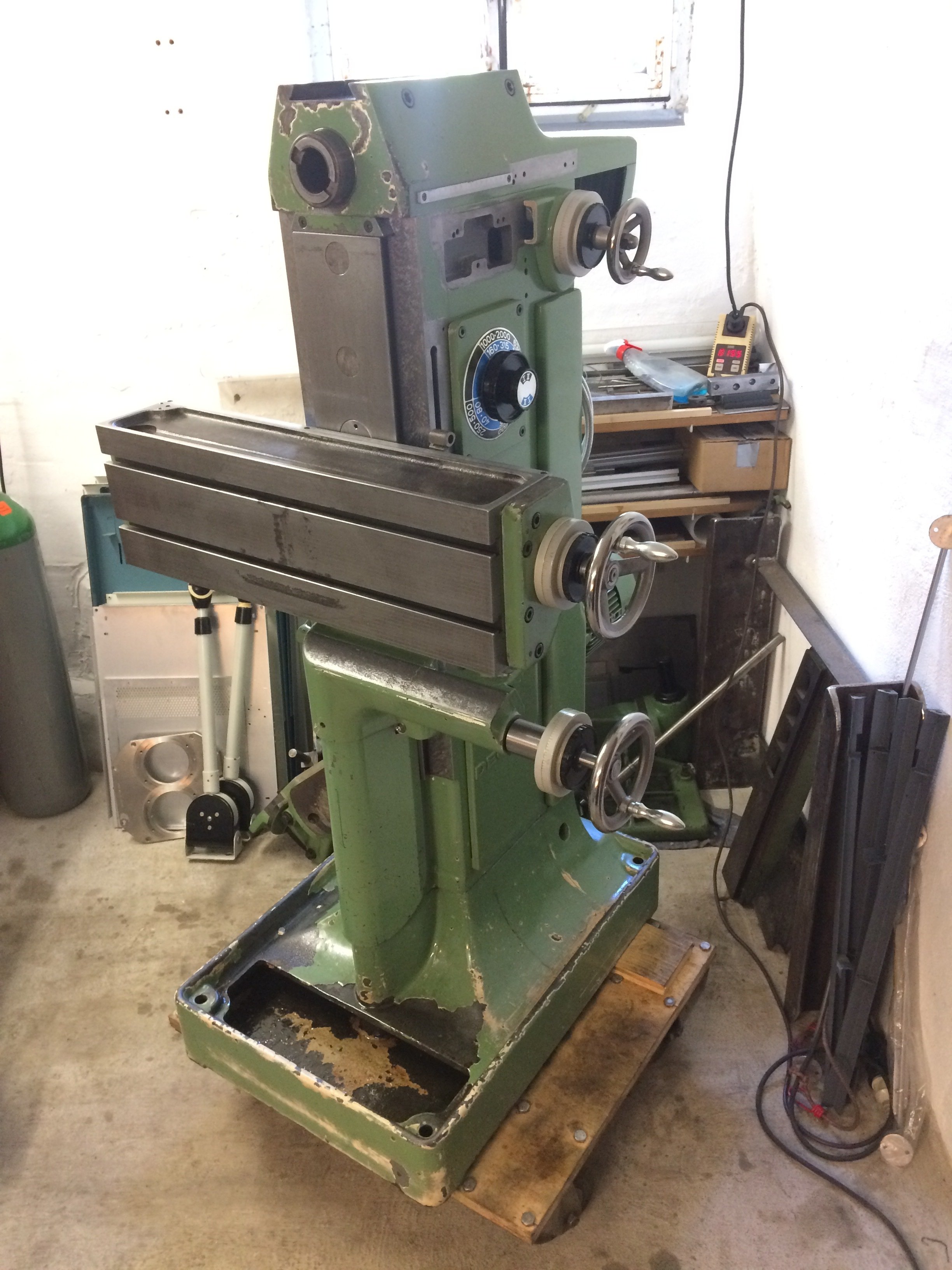
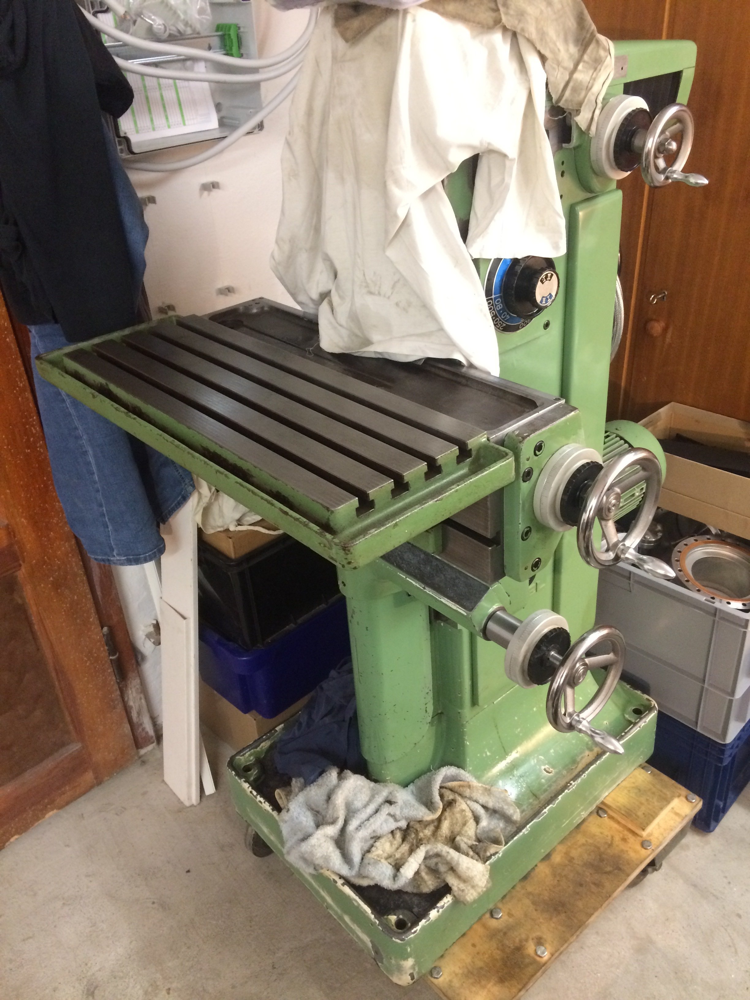
This is the FP1’s view now:
Overhaul #
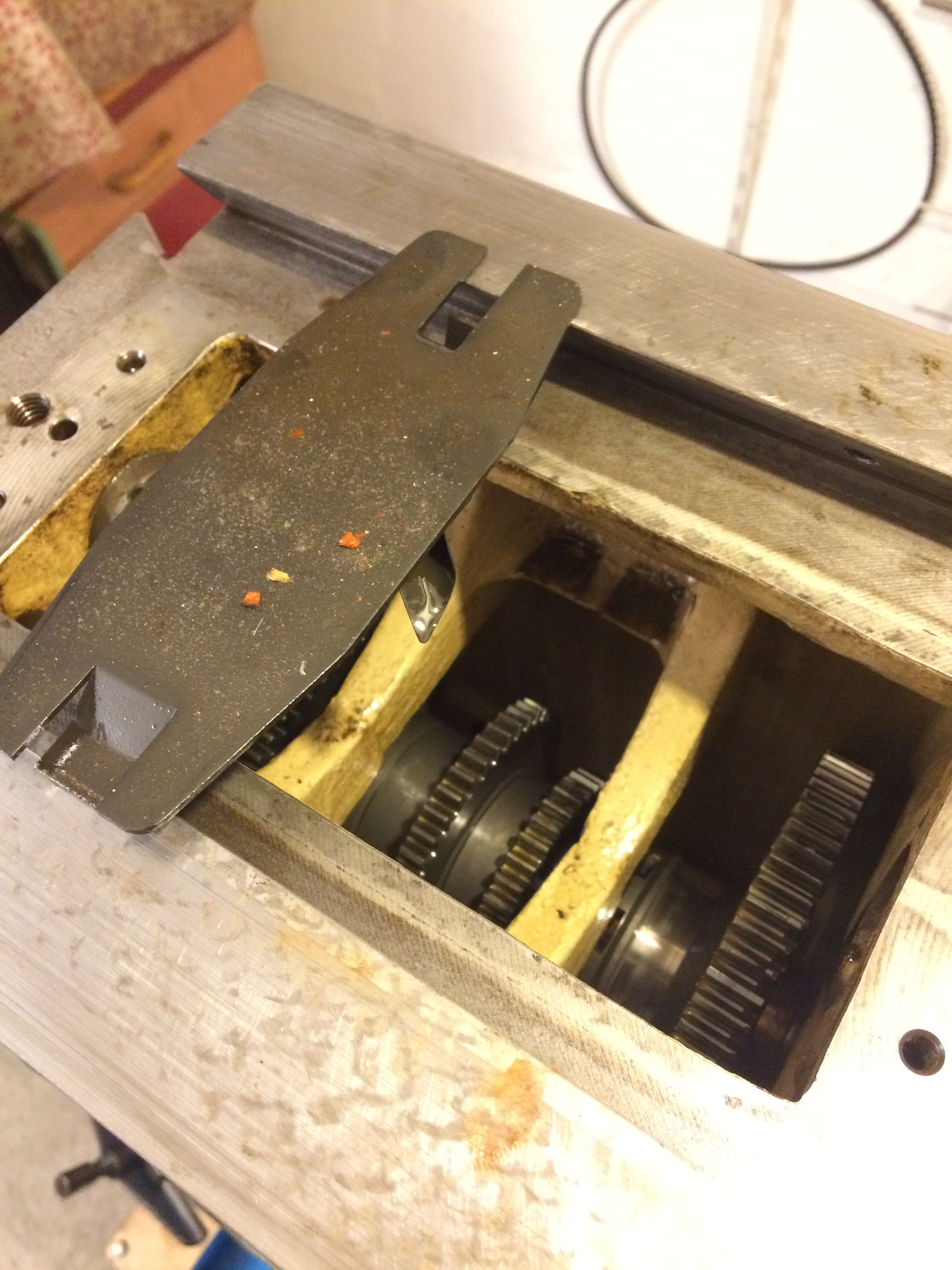
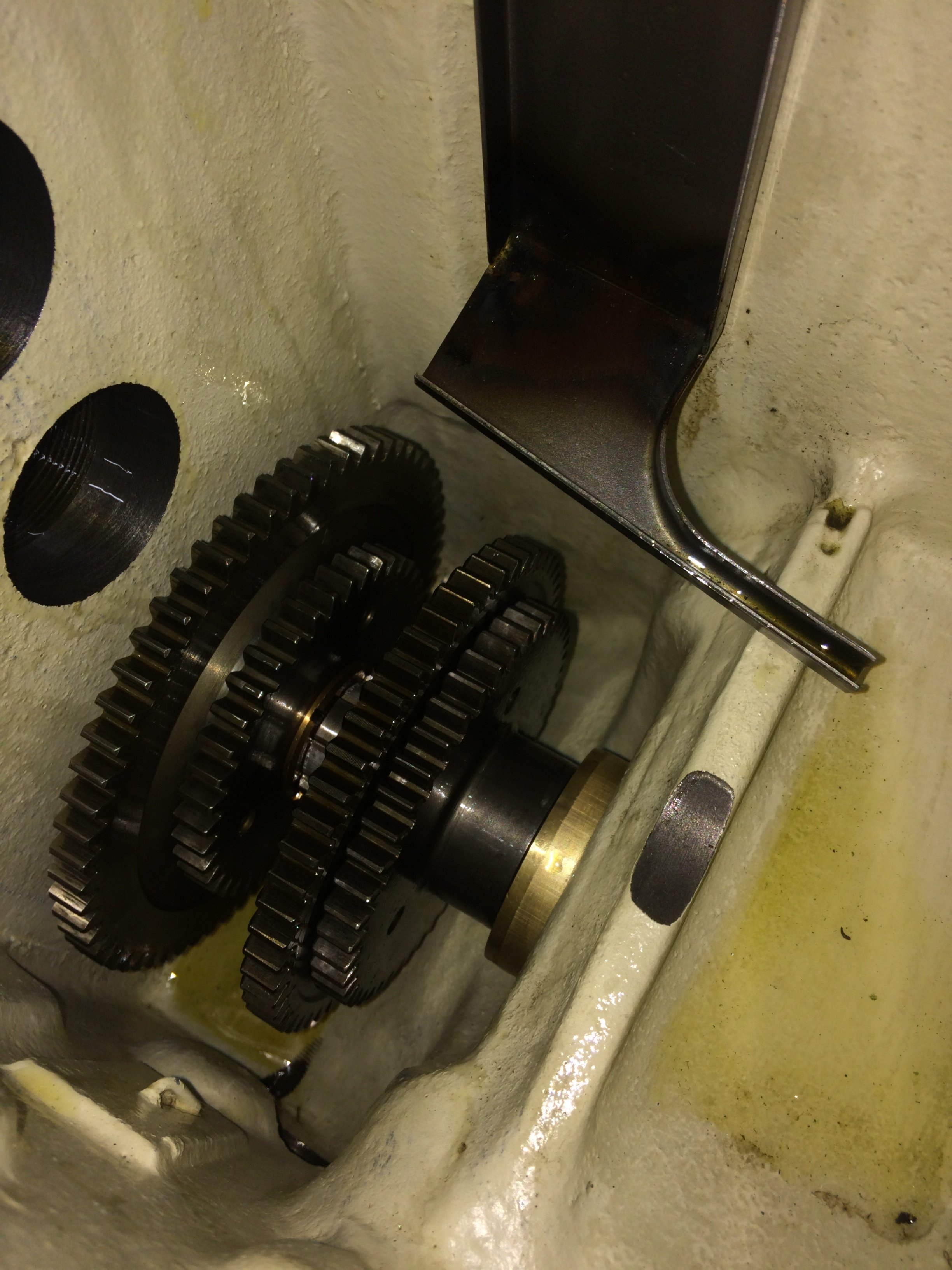
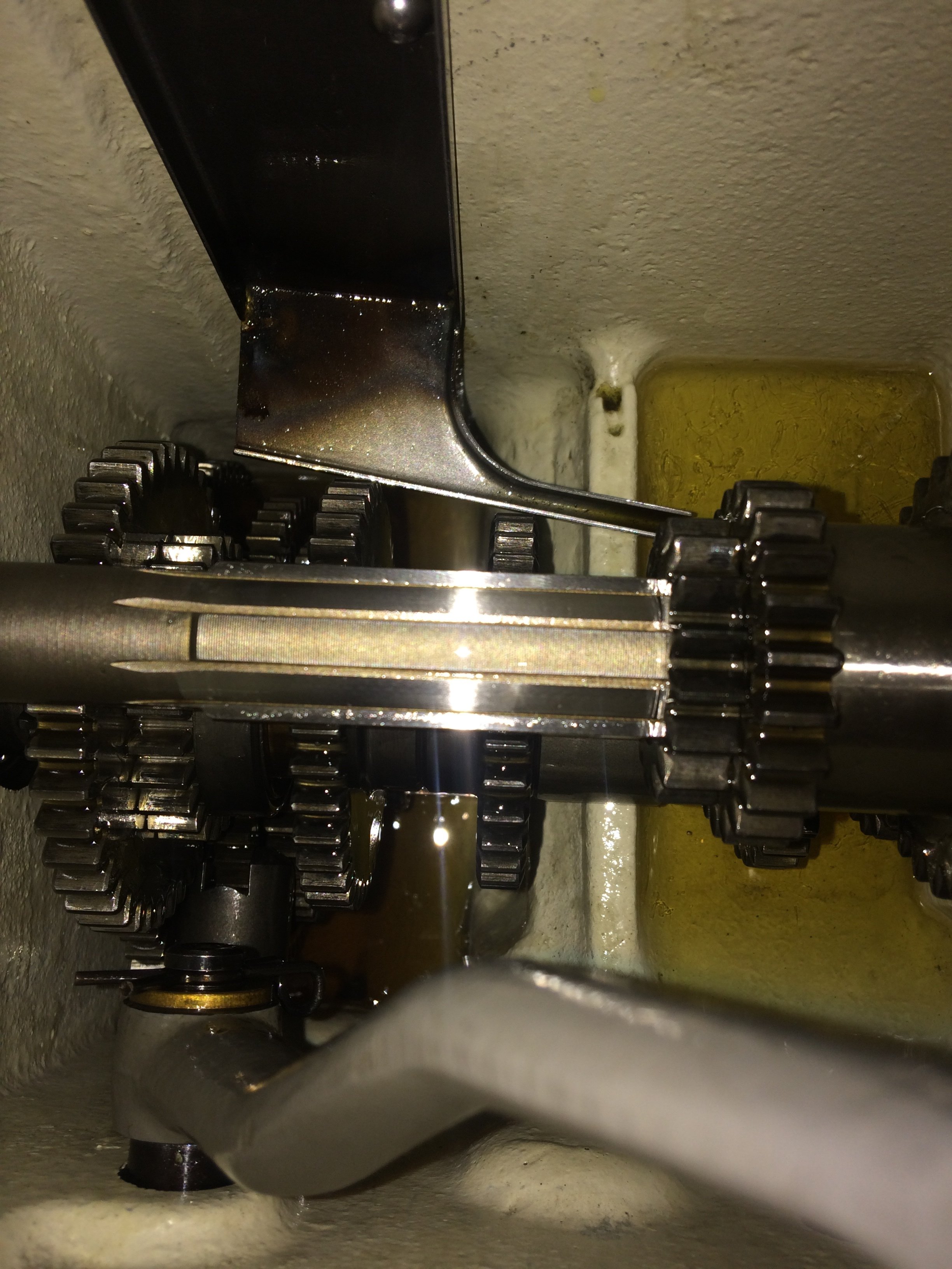
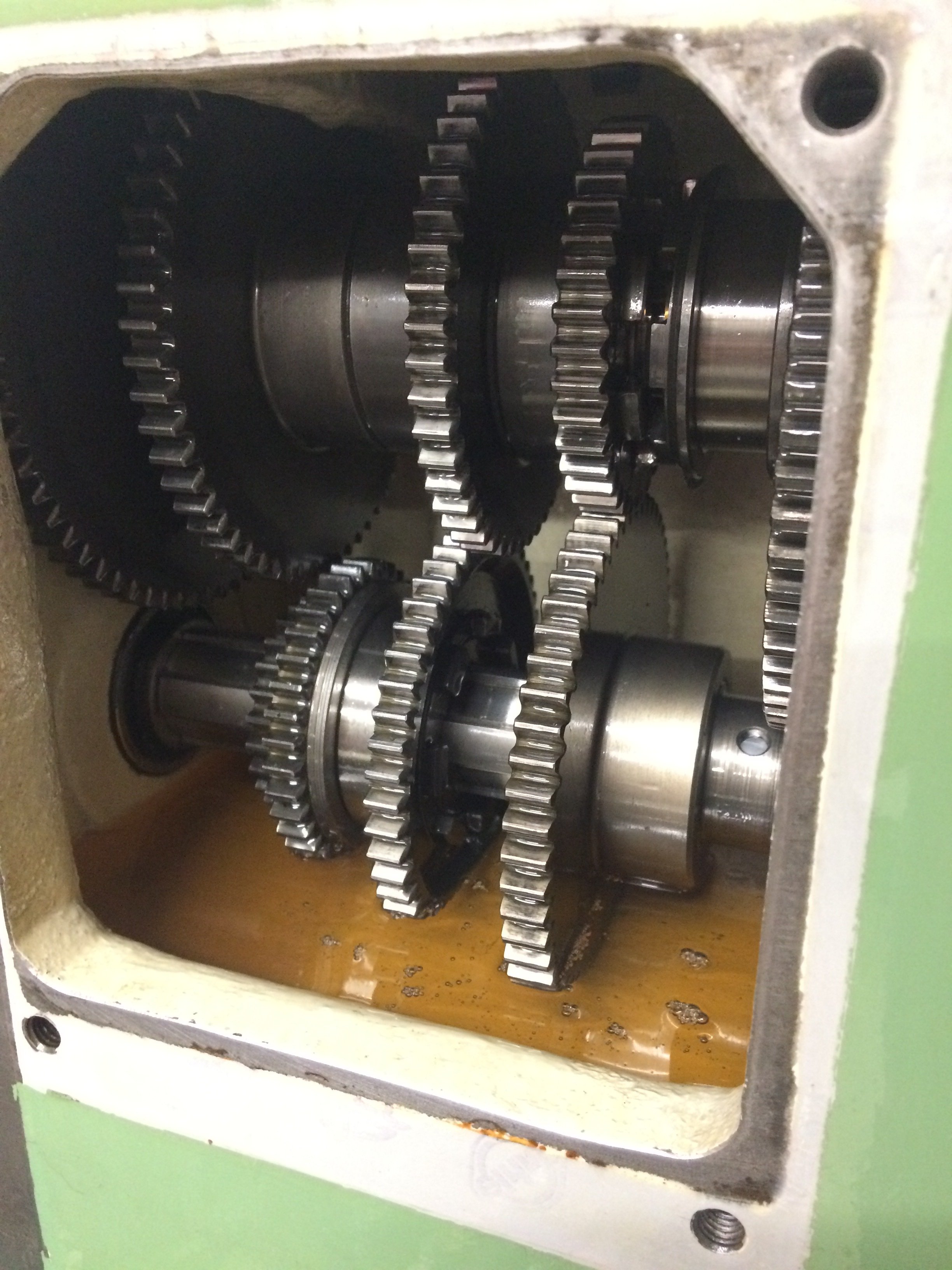
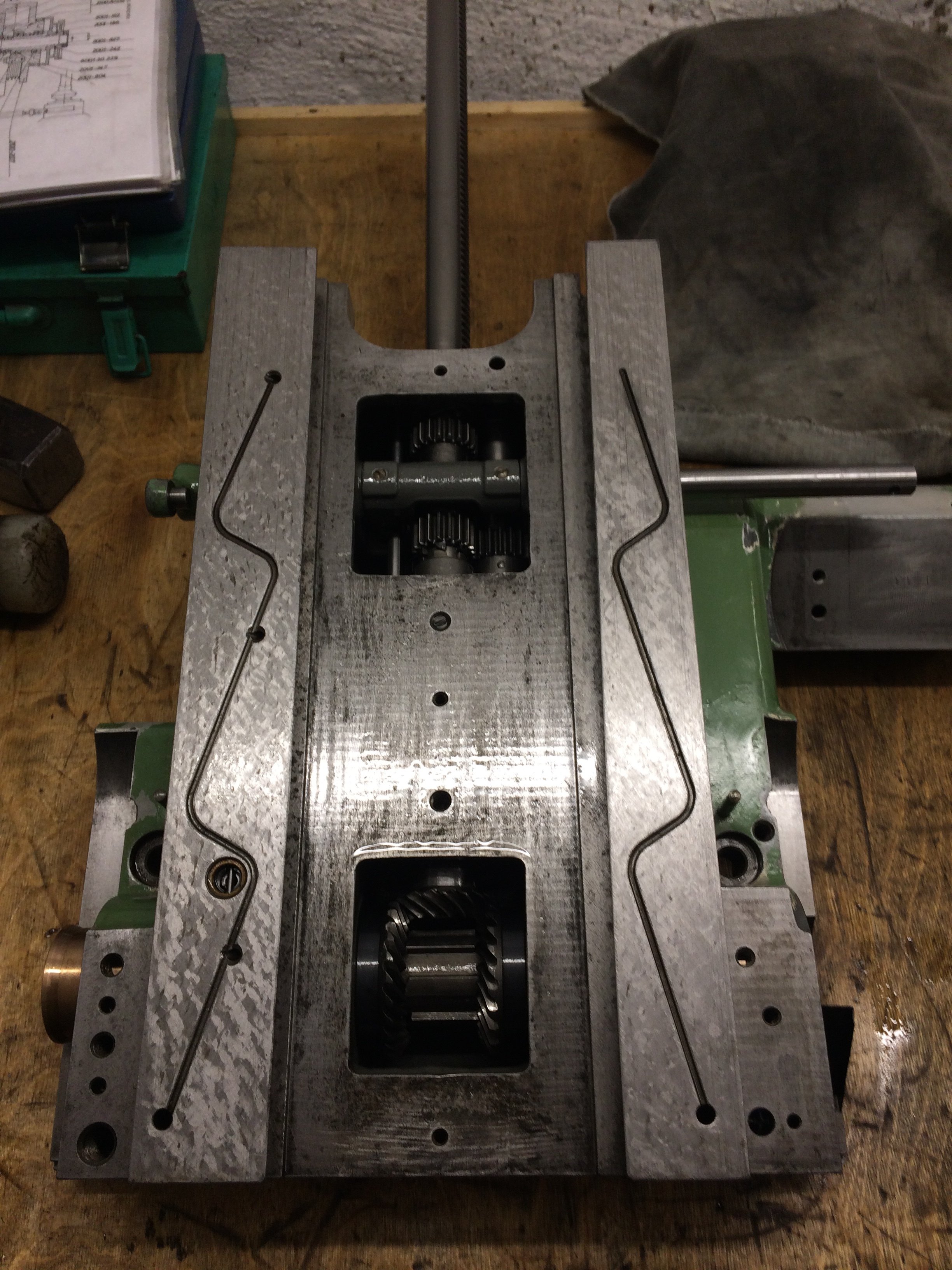
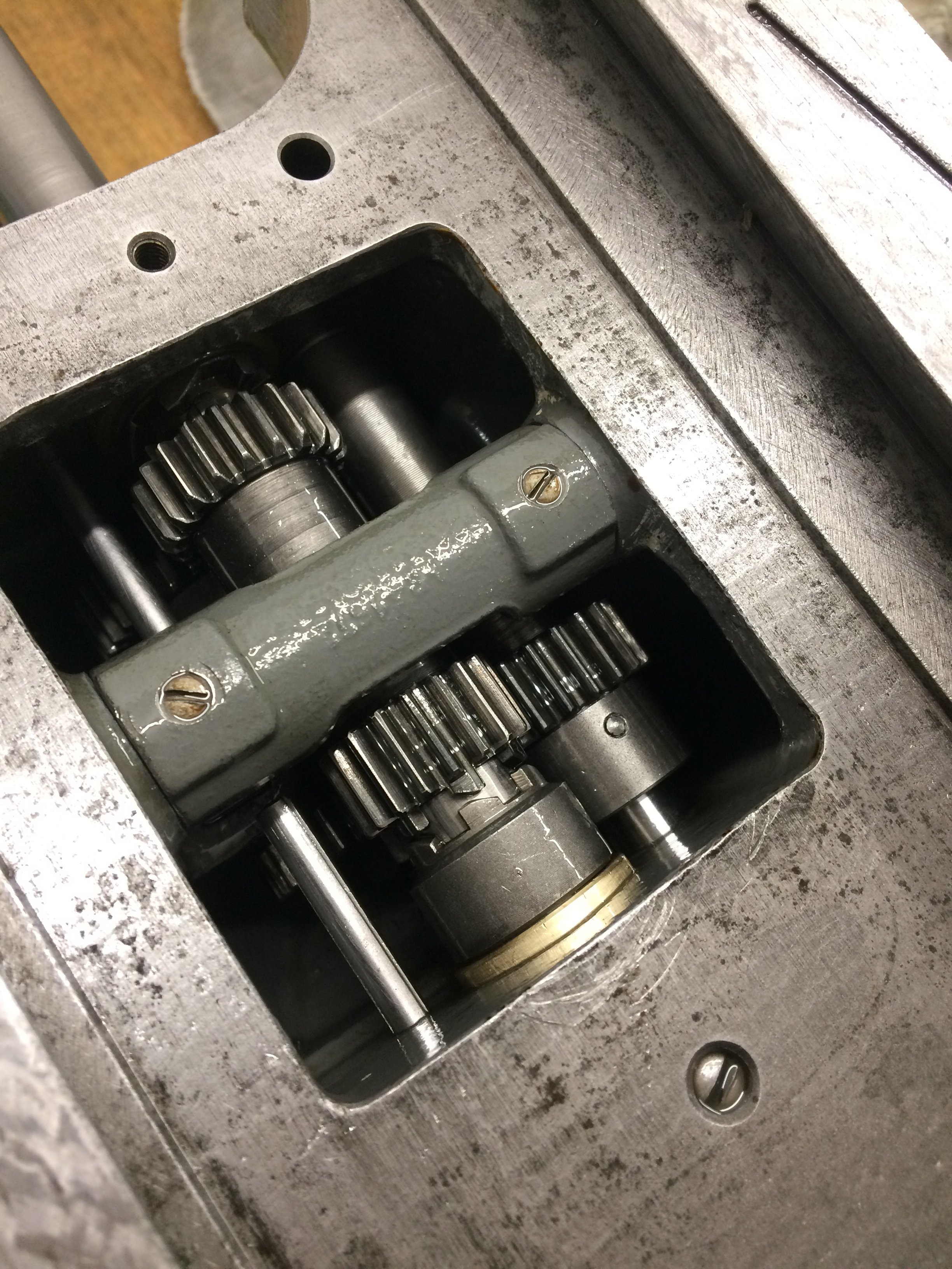
First a look at the milling/main gearbox …
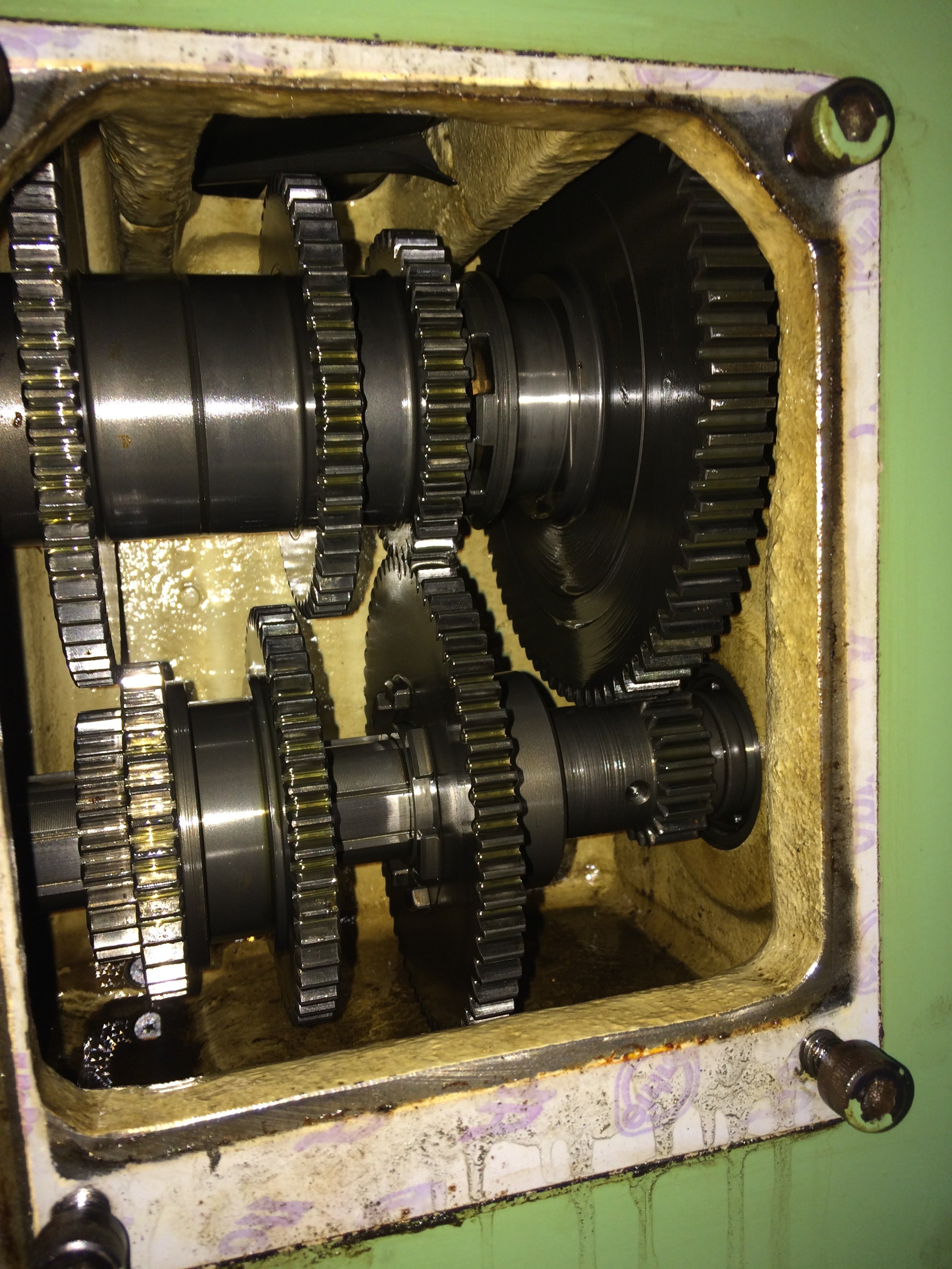
… and the feed gearbox:
All the little teeth are still there, all the little teeth, all of them :-)
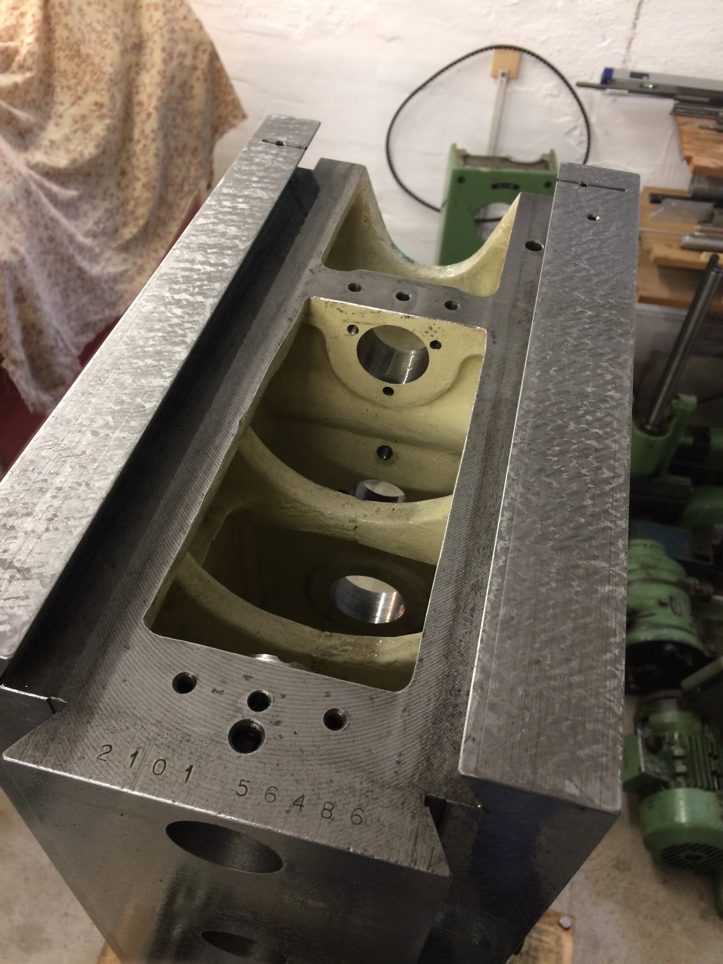
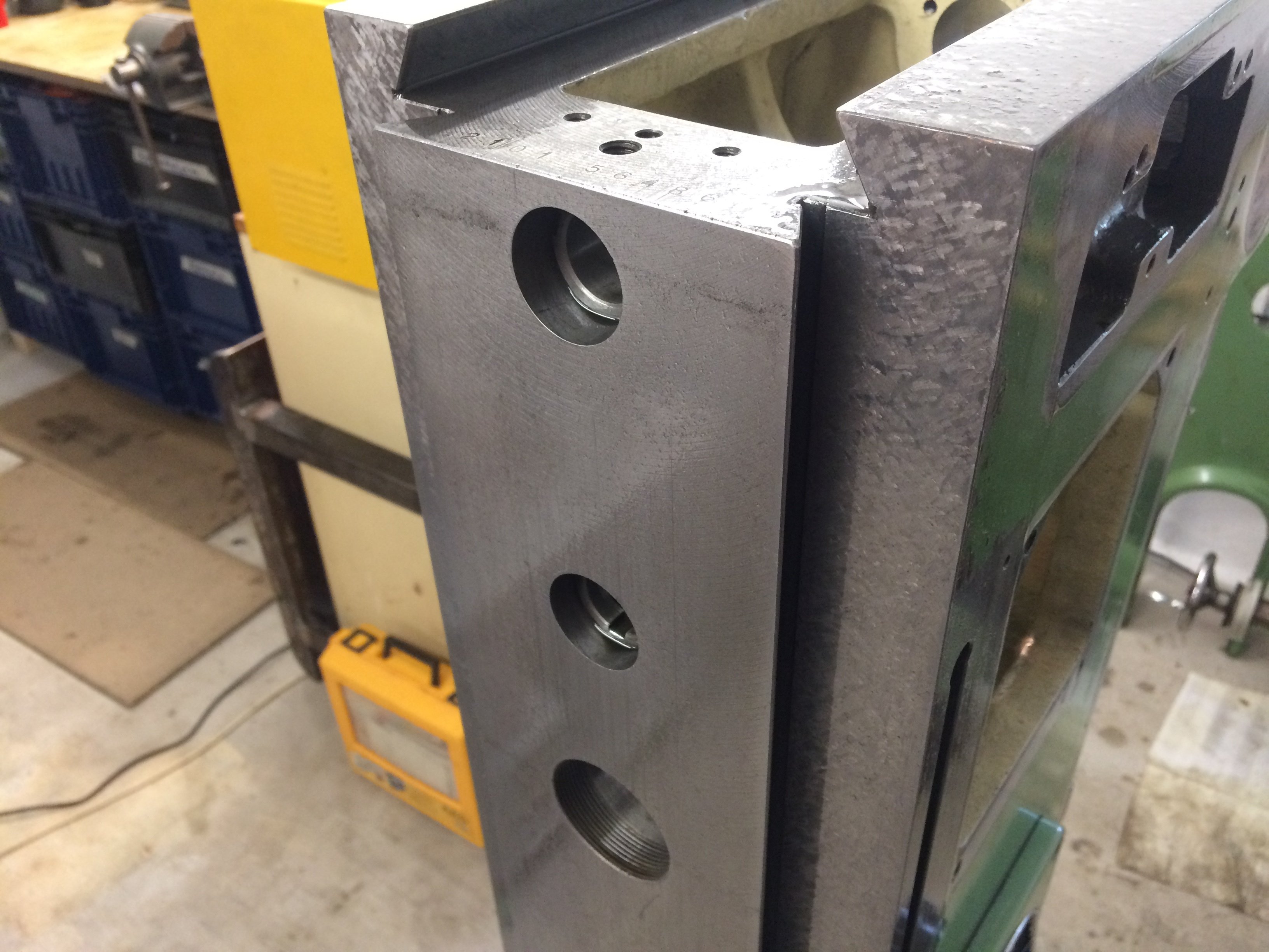
We continued at the back, where again plenty of dirt and grime were waiting for clean-up:
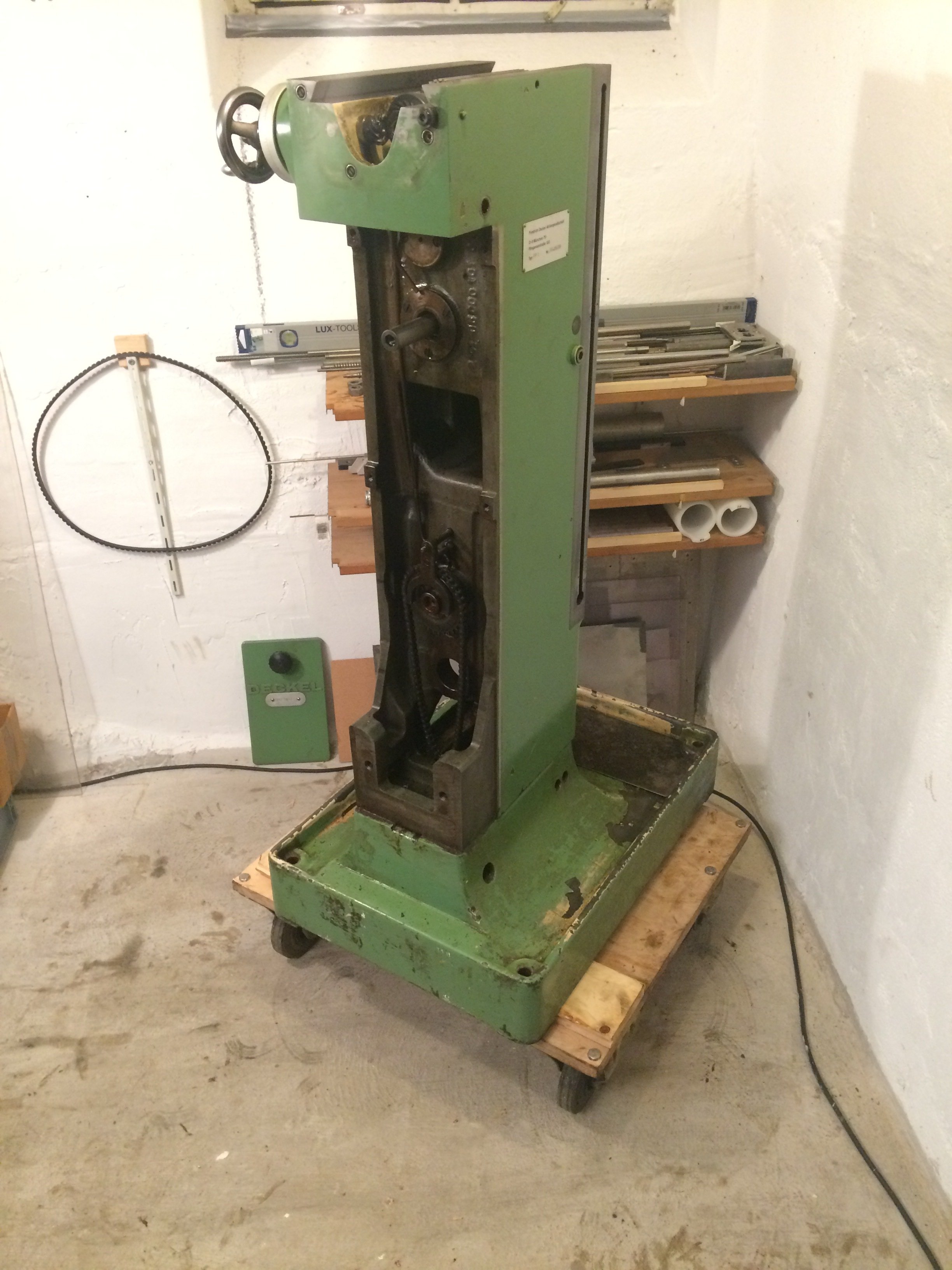
Bref oven cleaner and a bit of kerosene/lamp oil work wonders, though, and soon the rear is half-presentable again:
At the top of the main gearbox an oil-baffle plate (?) can be removed to get better access to the innards underneath:
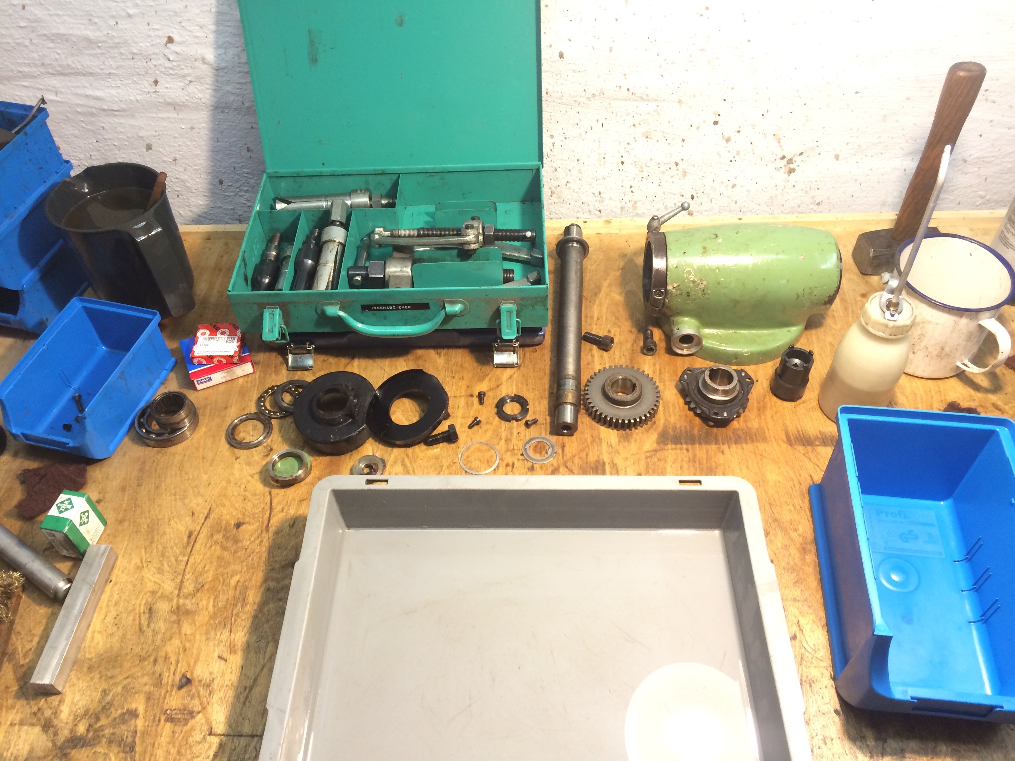
After an afternoon with a puller, ratchet set and pin spanner, the main gearbox lies in pieces on the workbench:
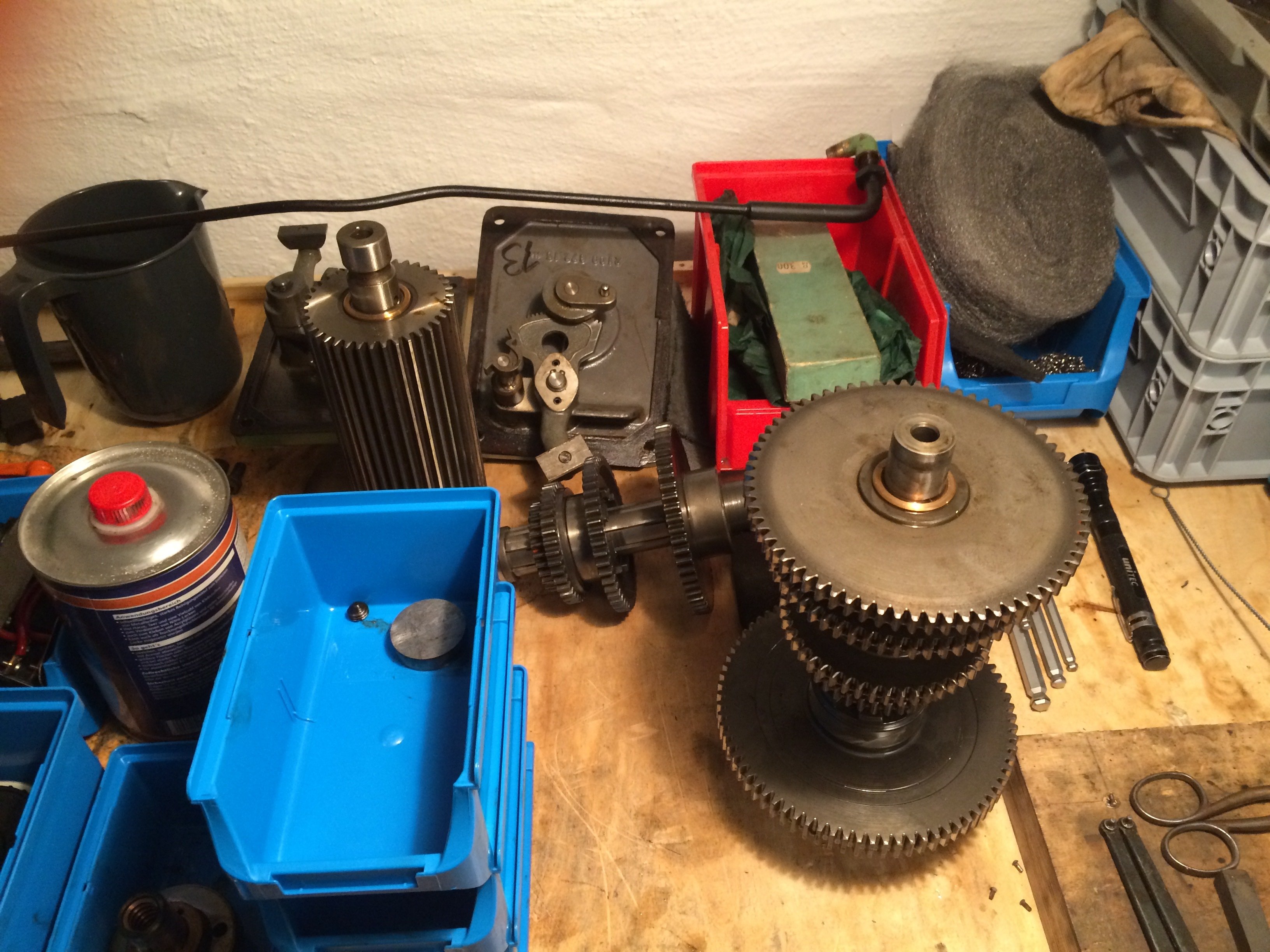
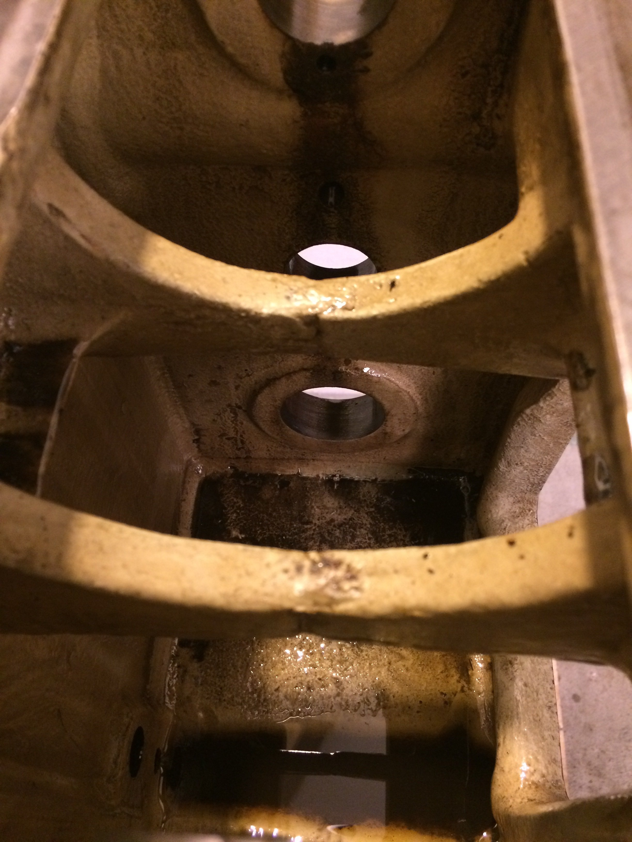
The space now accessible inside the gearbox housing invites a thorough clean:
A complete set of rolling bearings (with the exception of the selected spindle bearings) was procured ahead of time:
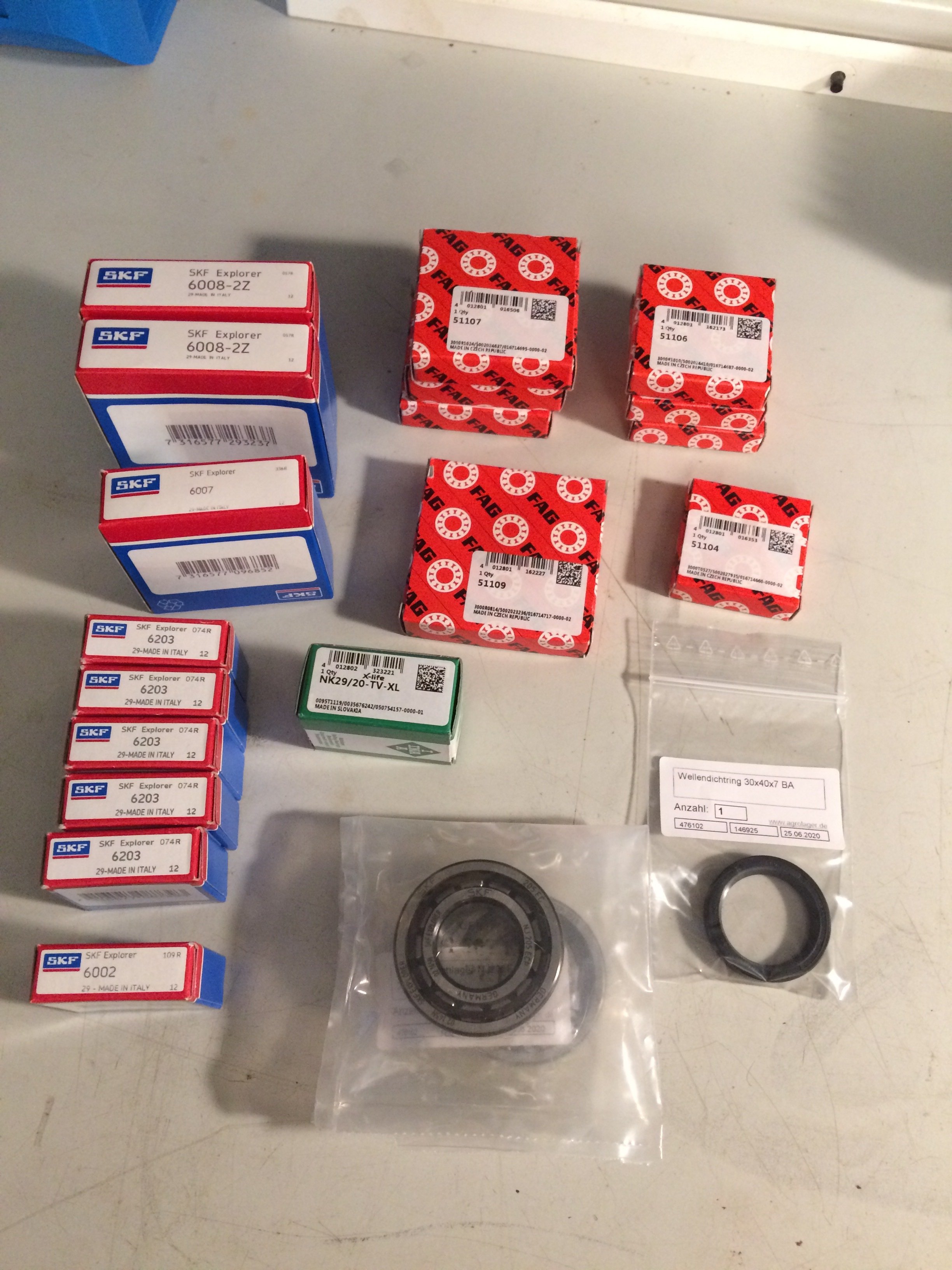
The prices refer to Agrolager’s offer; I’m not related to or in cahoots with them, just had good experiences there. No idea why the oil seal is missing from the order list – probably I only noticed it relatively late.
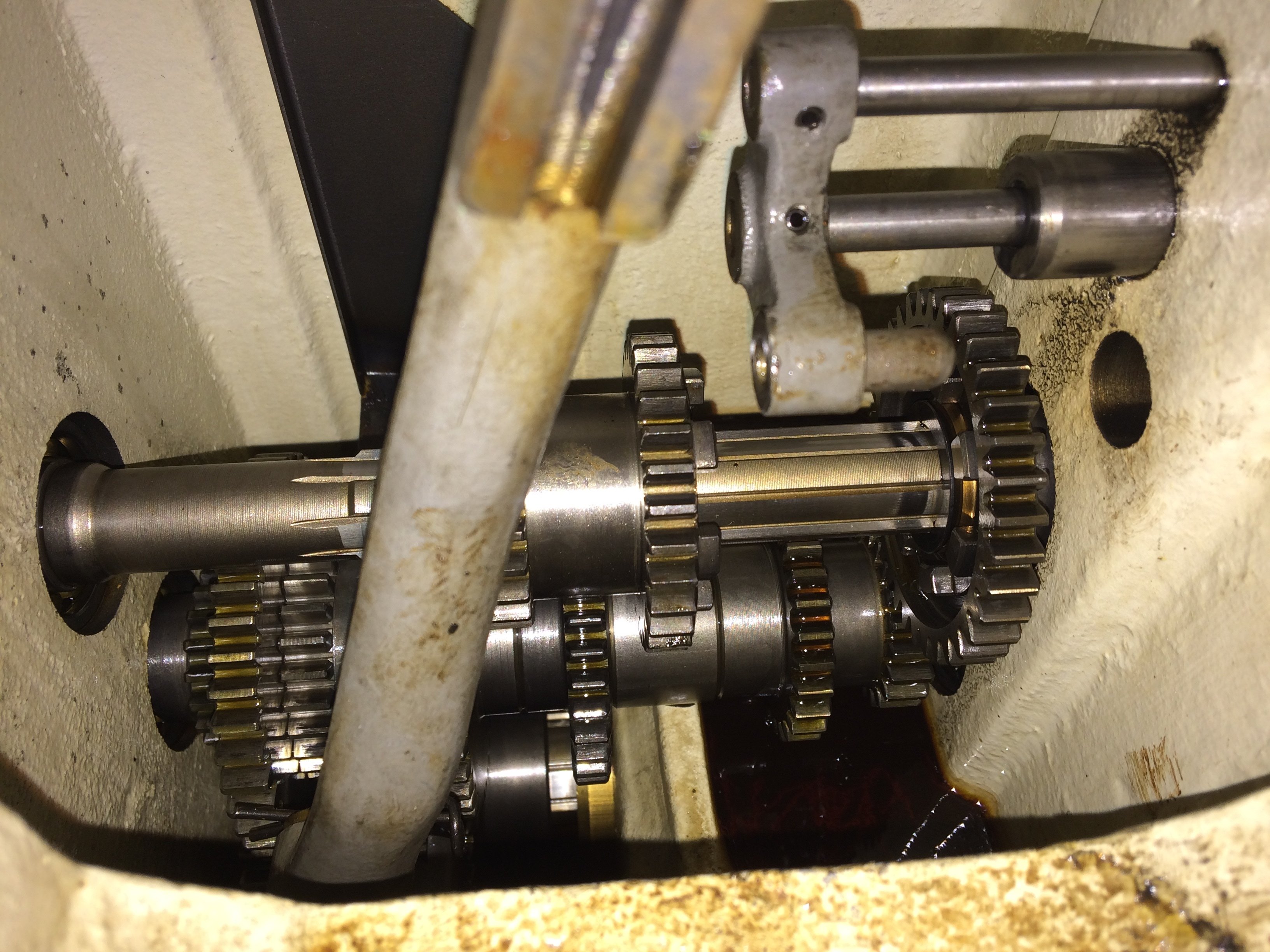
The feed gearbox was also dismantled. I cleaned the gearbox parts by hand in a kerosene bath using a brush, wire- and toothbrush, and abrasive pad, and then re-oiled them. For the assembly order I refer to Marc’s report part 2, which describes the individual steps in extreme detail.
We start the assembly with the lowest shaft in the feed gearbox:
Two more shafts follow:
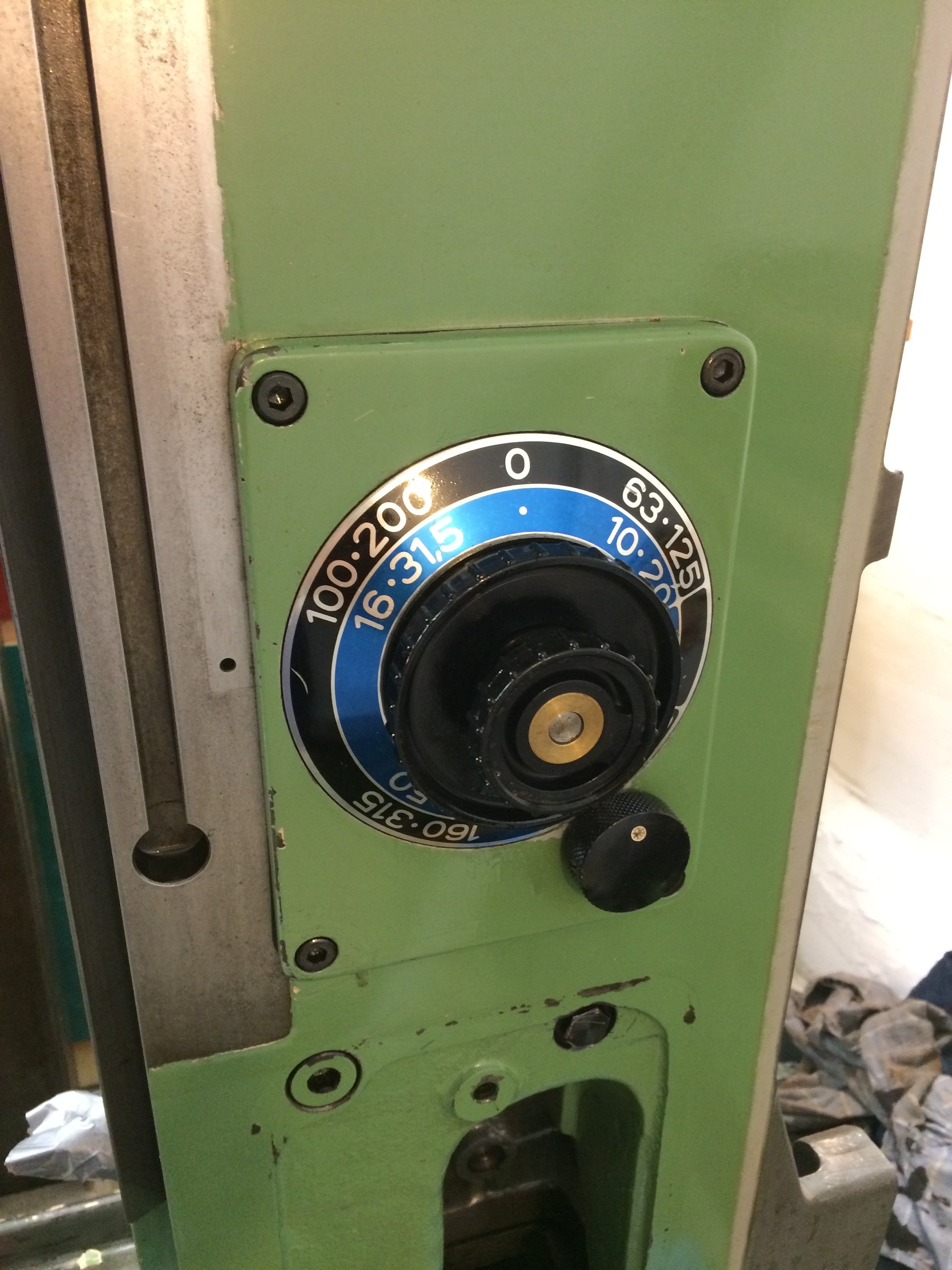
“Curtain down, monkey down” – the feed gearbox is back together :-) The dial with scales, etc., was also taken apart and given a kerosene bath. The missing “I/II” scale for the inner shift lever I still need to order…
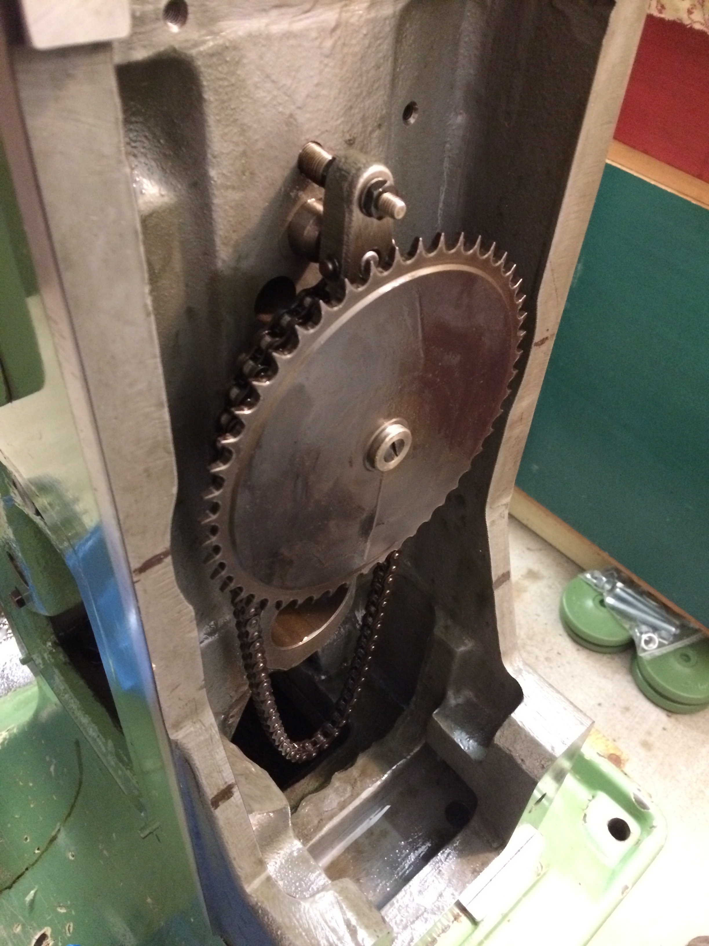
Next, the chain to drive the coolant pump can be re-fitted:
Now the blasphemy begins, and I apologise in advance to those readers who may faint at what follows!
I’d already decided at the outset of this project that this would not be a complete geometric overhaul. Firstly, because I found only mild wear on disassembly, and secondly, because I simply don’t have the time for it right now. On “used” machines I have always reached my goals, and I’m fairly confident that with this FP1 too I’ll be able to make plenty of nice parts over the next few years without having scraped it from the ground up first. Don’t get me wrong – I do want to do that some day in the future, but the time has to be there and I need to develop my scraping skills further.
In the current state, however, the scraping marks were already largely gone, and so I decided to at least open up all the sliding surfaces once crosswise and once lengthwise with the Biax to give the oil something to hold onto and somewhere to go. Here on the Y way…
… and on the Z way:
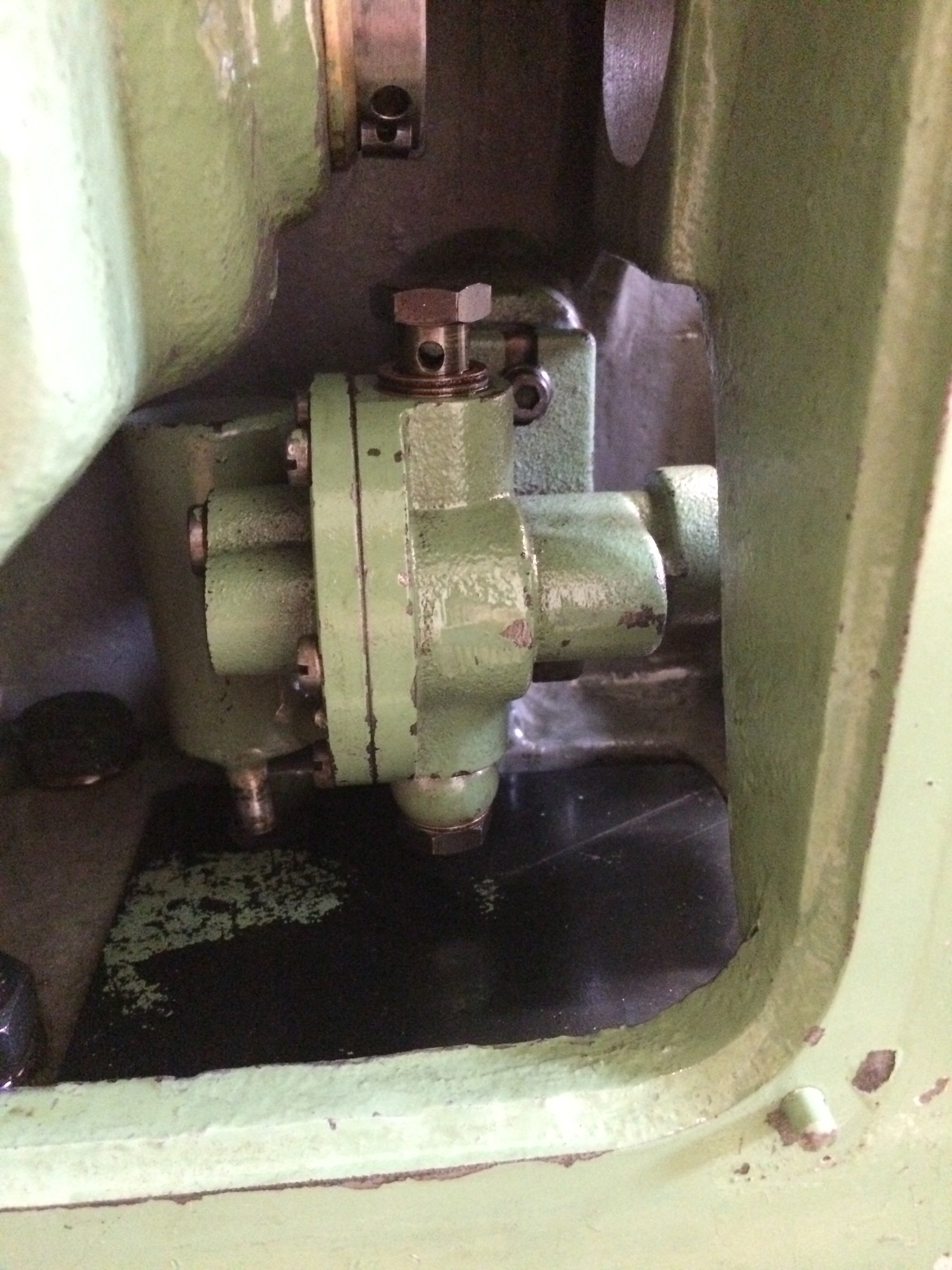
I also re-fitted the coolant pump, although I probably won’t use it much (a Dynacut MMQL is available):
The main gearbox was then re-assembled and filled with oil. The rotation of the gears transports oil upward and also lubricates the Y axis. So I filled it with CGLP-68 (slideway oil), which is intended for ways but also lubricates the gears well:
Cover on, and the main gearbox is also fit for service:
The Y-axis spindle nut was reinstalled from the back into the hollow gear shaft, and the corresponding handwheel mounted:
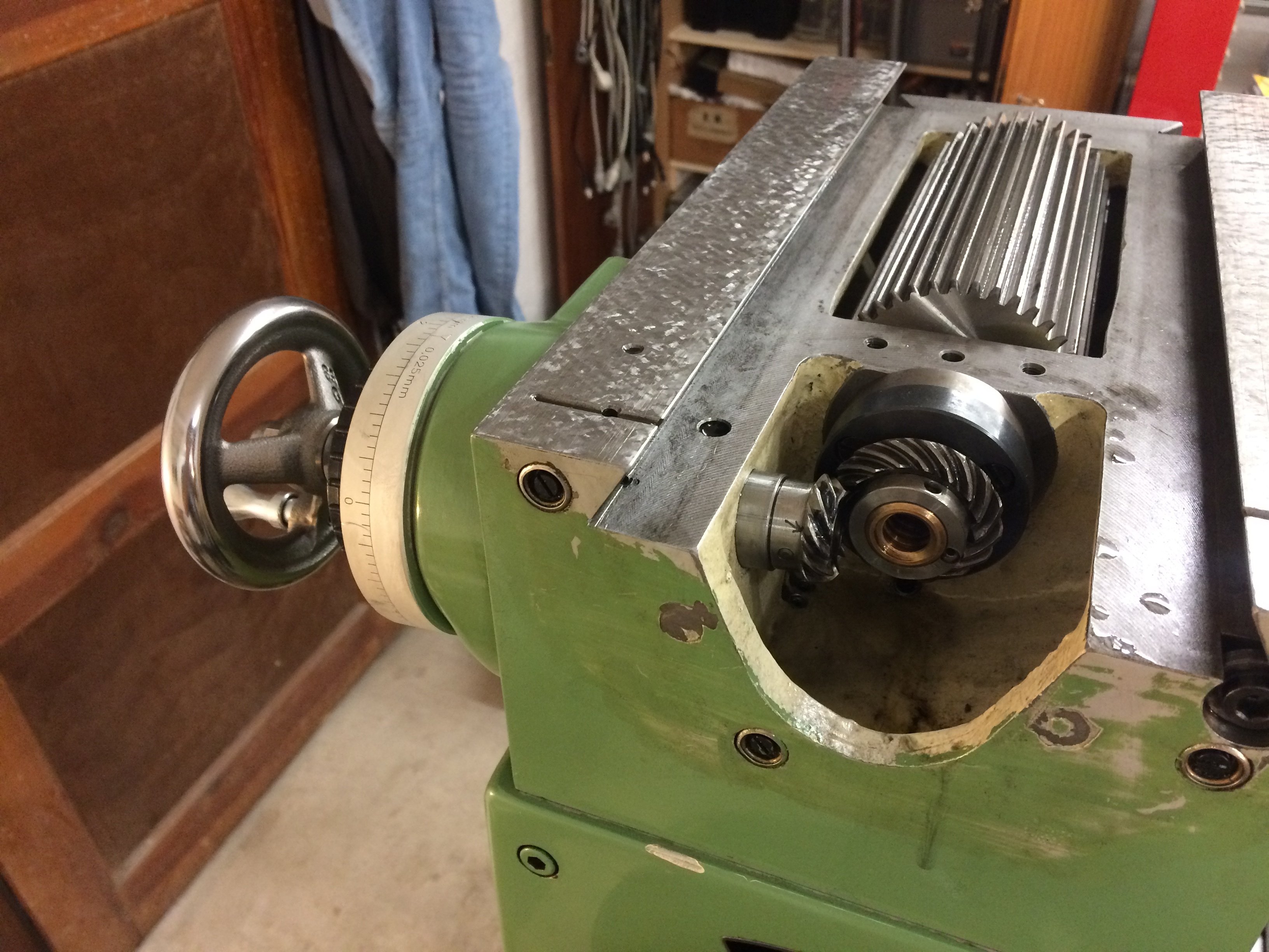
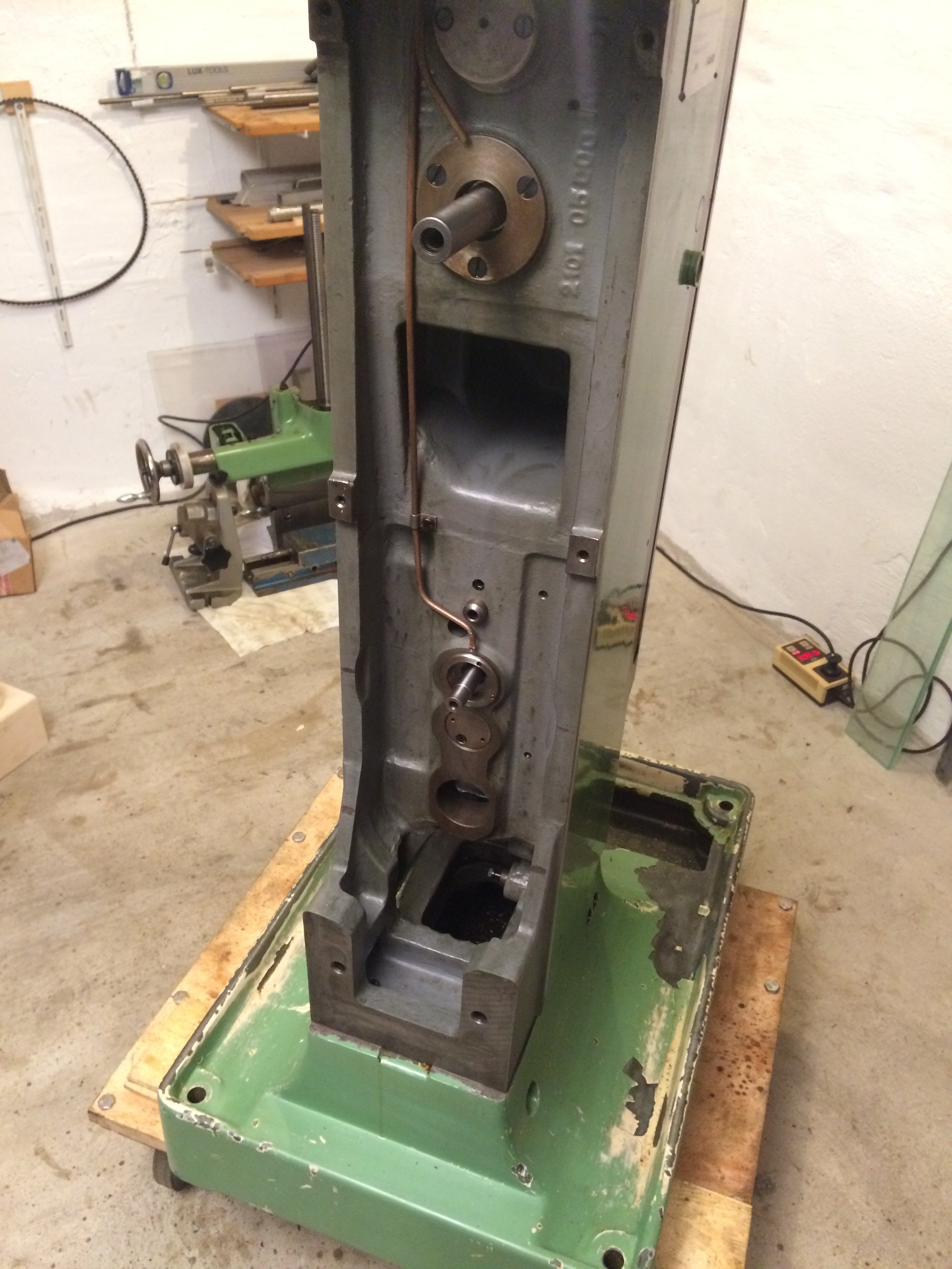
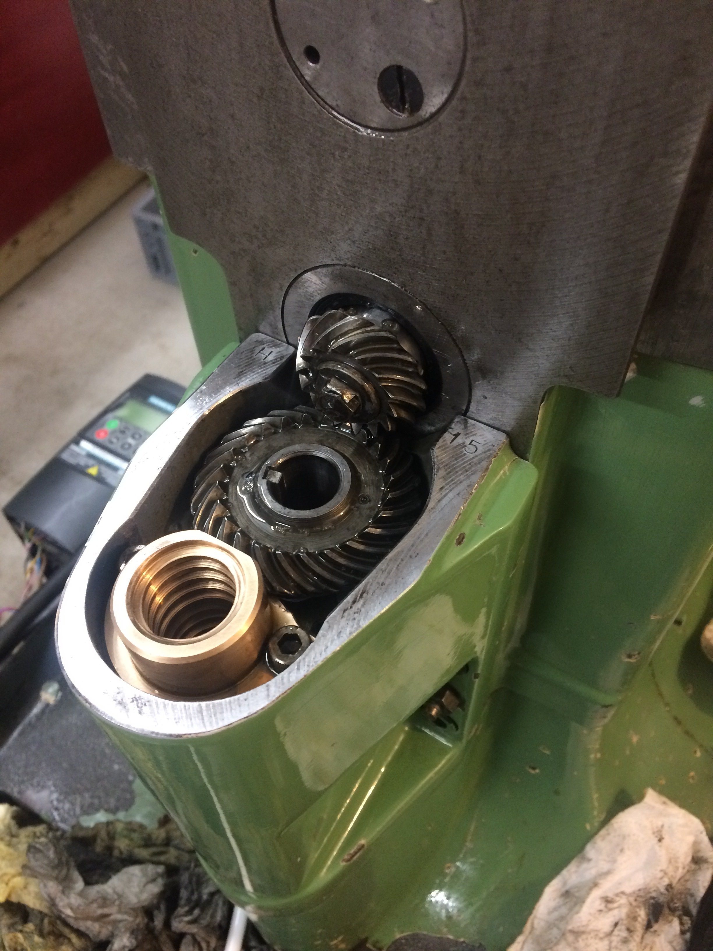
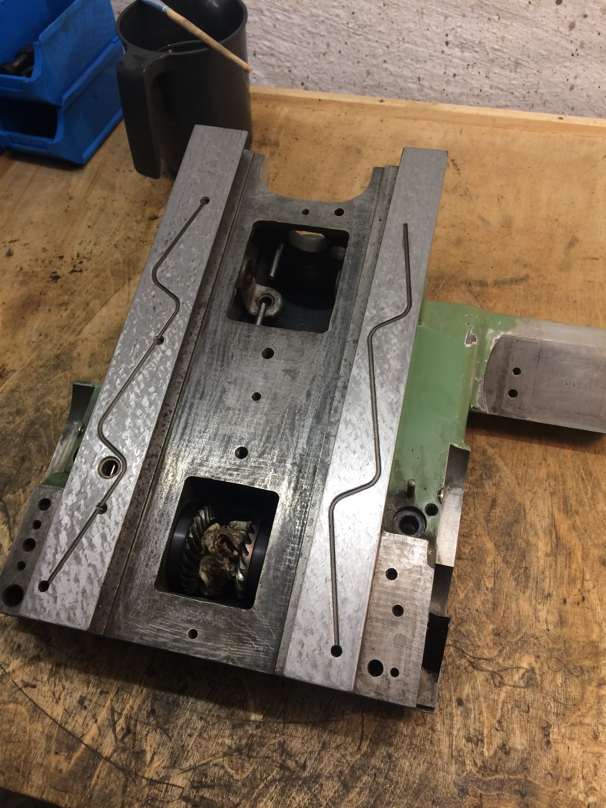
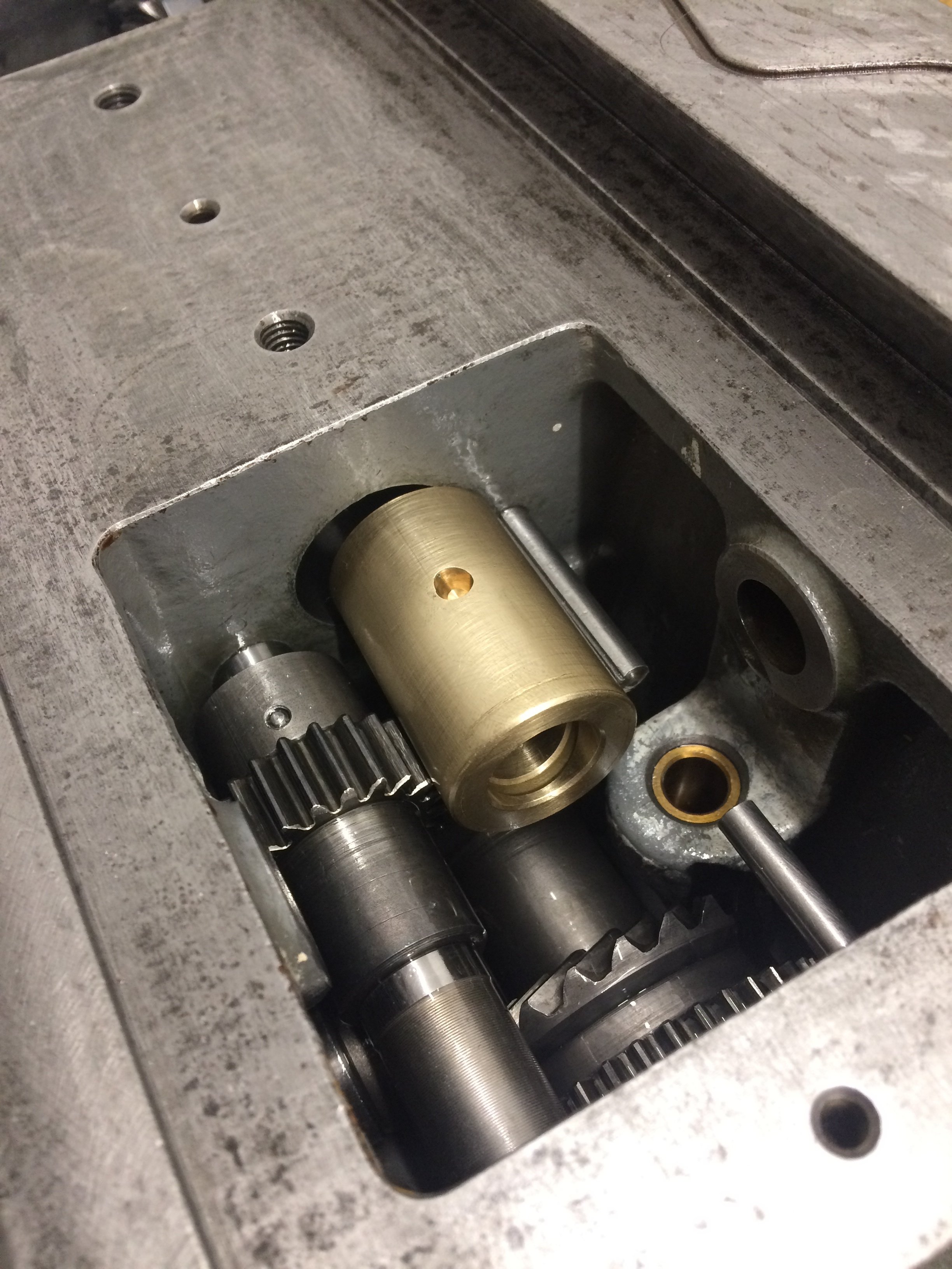
At the front-bottom of the column, the bevel-gear box / knee attaches, into which the Z spindle and the feed shaft (which protrude from the bottom of the knee) plunge. The horizontal bevel gear in this assembly, by the way, had seized in the bronze bushing it’s supposed to run in. That had caused the feed to lock up and the shear pin to break. A lot of coolant gunk had built up here from earlier use, and it had gradually displaced the oil…
That largely concludes the column.
The next subassembly was the Y slide with the horizontal spindle. First, the horizontal spindle and its bearings were removed for inspection:
There was some dirt, but the needle cages and corresponding running surfaces still looked OK. A look from above into the Y slide:
The parts were packed individually and waited for the return of the vertical quill from Austria, since a tube of LDS18 would be included with the return shipment, as I knew from a reliable source.
This isn’t the SuperTEL that Deckel originally specified for the needle-bearing spindles, but seems to be the next best, currently available product. I use the horizontal spindle much less and the previous owner probably also used it much less for milling, so I assume the bearings are still in good shape and will probably live a long time even if they only get the second-best lubricant currently available worldwide for this application…
Next, the knee was emptied and cleaned. Here too, the ways were “broken open” again by criss-cross scraping:
The knee is (in my opinion, and not only mine) the most demanding subassembly of an FP1. You can see that just from the sheer number of parts in it:
Bad luck if you don’t think the assembly order through carefully…
But in the end everything ends up where it belongs:
Ah, that looks much more inviting now:
A few other small bits and the knee can be slid back onto the Z axis of the column:
After fitting the horizontal spindle into the Y slide, that too can be mounted on the machine again:
The X slide is also a piece of work. Mostly it’s about removing the dirt of the past and equalising burrs and dings. I crisscrossed the sliding surfaces of the X slide once each as well, to give the oil somewhere to go. Mounted on the machine, it almost looks like a mill again:
A few nice new bellows were available on the Zerspanungsbude forum:
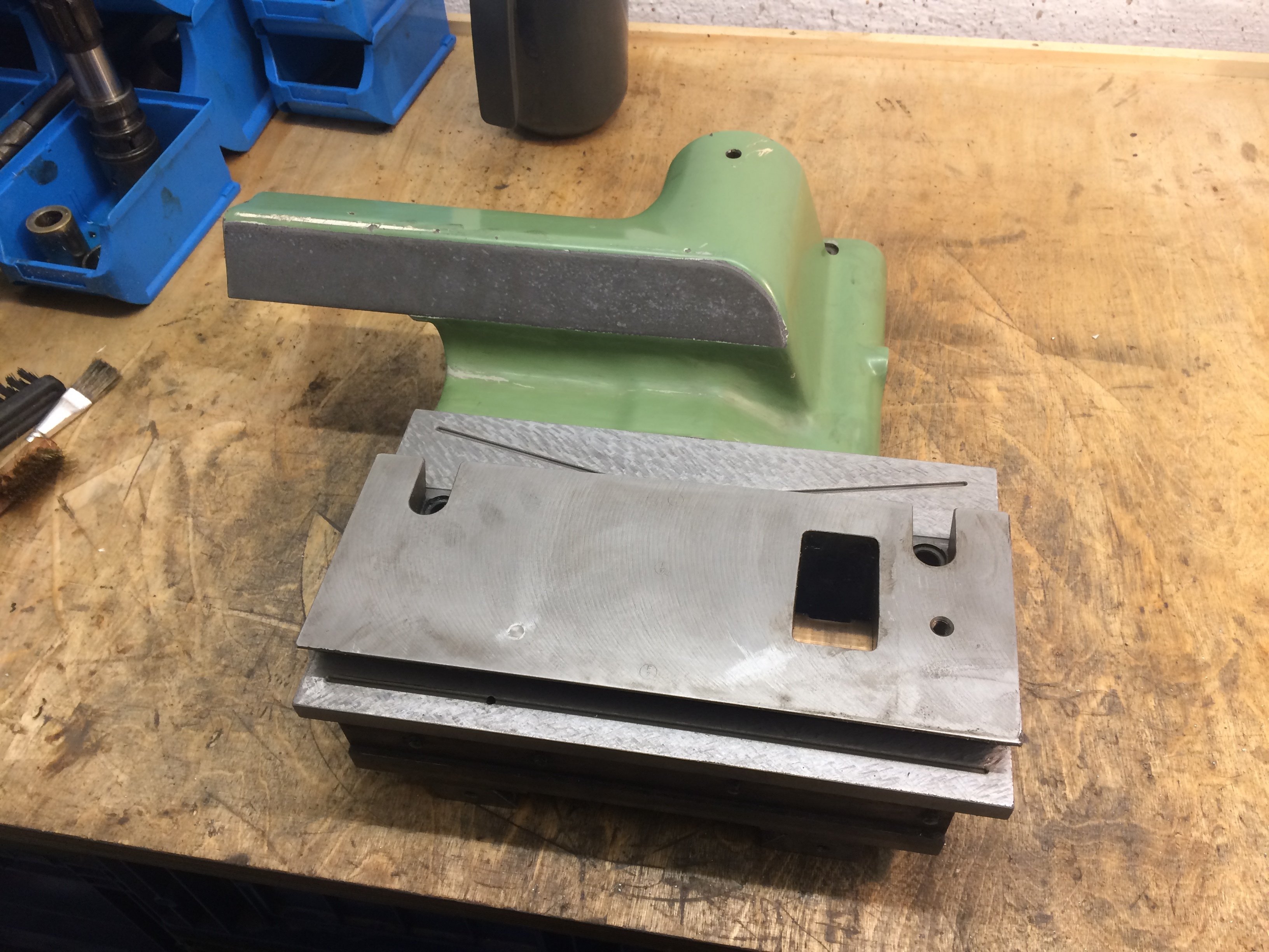
The fixed angle table was pleasantly part of the deal and shines anew now:
The universal swivel table is currently still apart, since the table top has quite a few dings. I want to send the table top out for re-planing, but haven’t got around to it yet…
Vertical spindle #
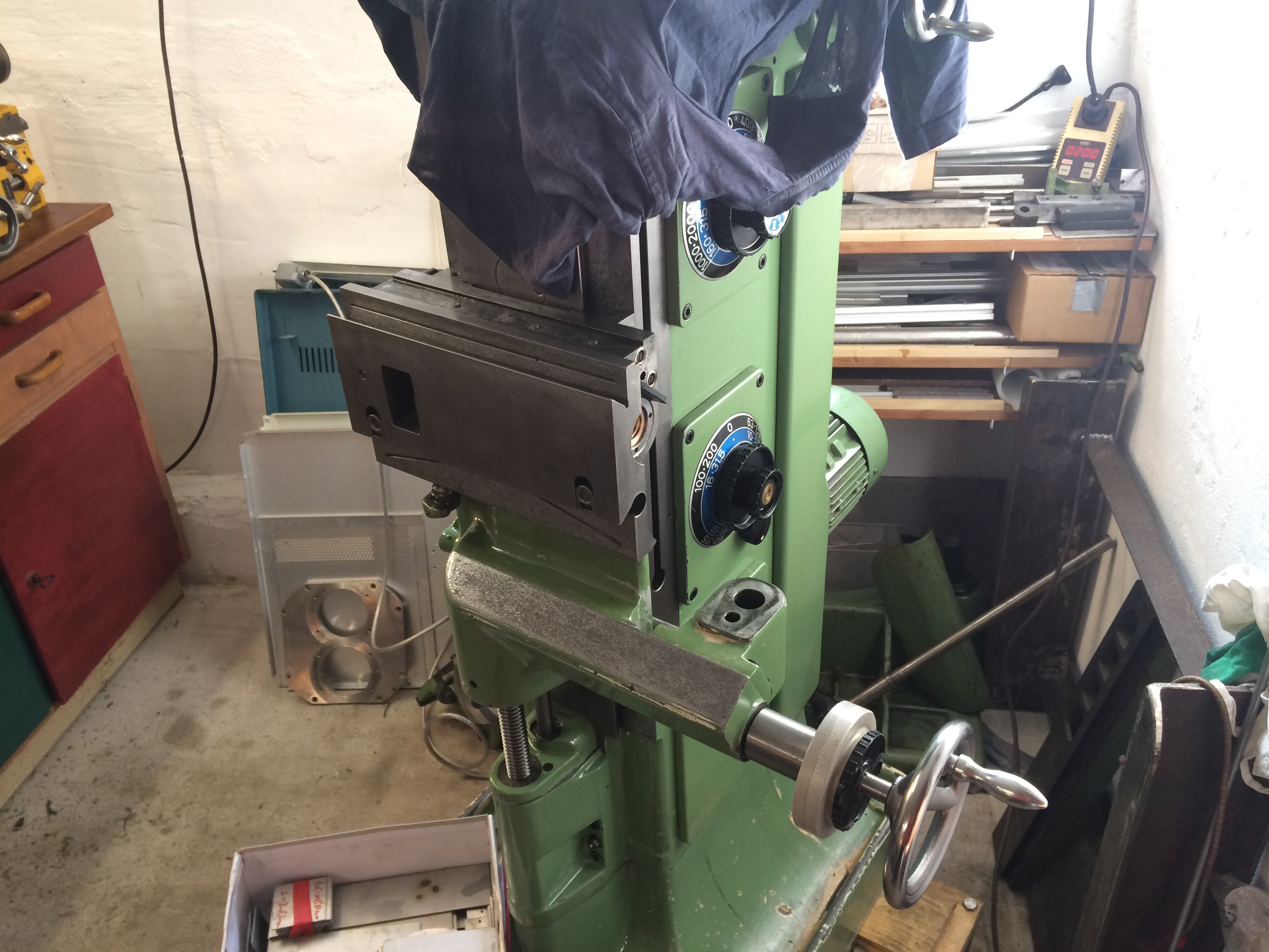
The vertical head was the last subassembly outstanding. The “main piece” was reasonably easy to clean and, after cleaning, took up a quick test fit:
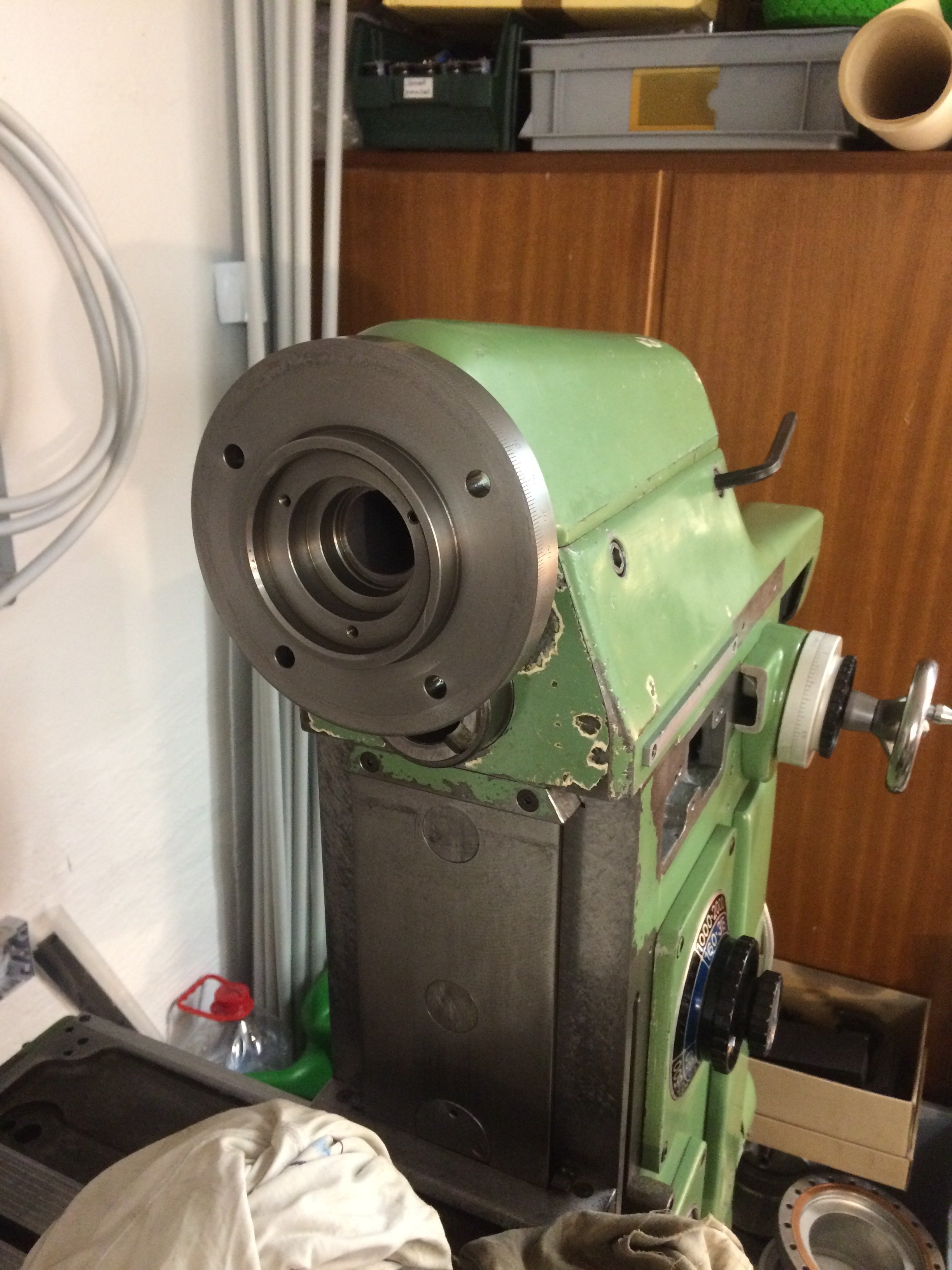
Inside, of course, some linkages are still missing – at this point they were still in the wash:
Tightening and loosening the screws holding the gears on the shaft required some creativity:
And then it went “plop” (why? because it just went “plop” …) and the horizontal portion of the vertical milling head was back on the machine:
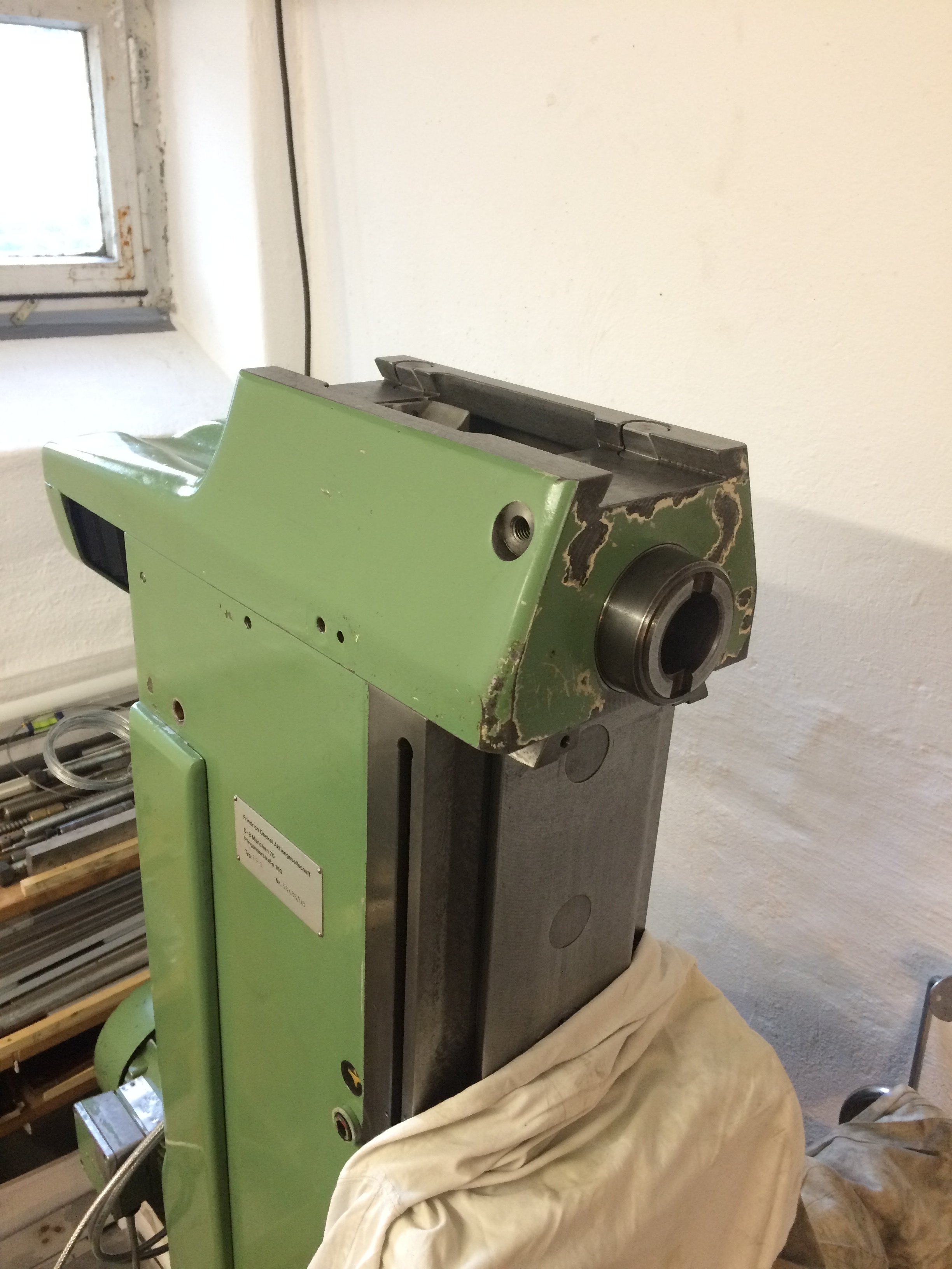
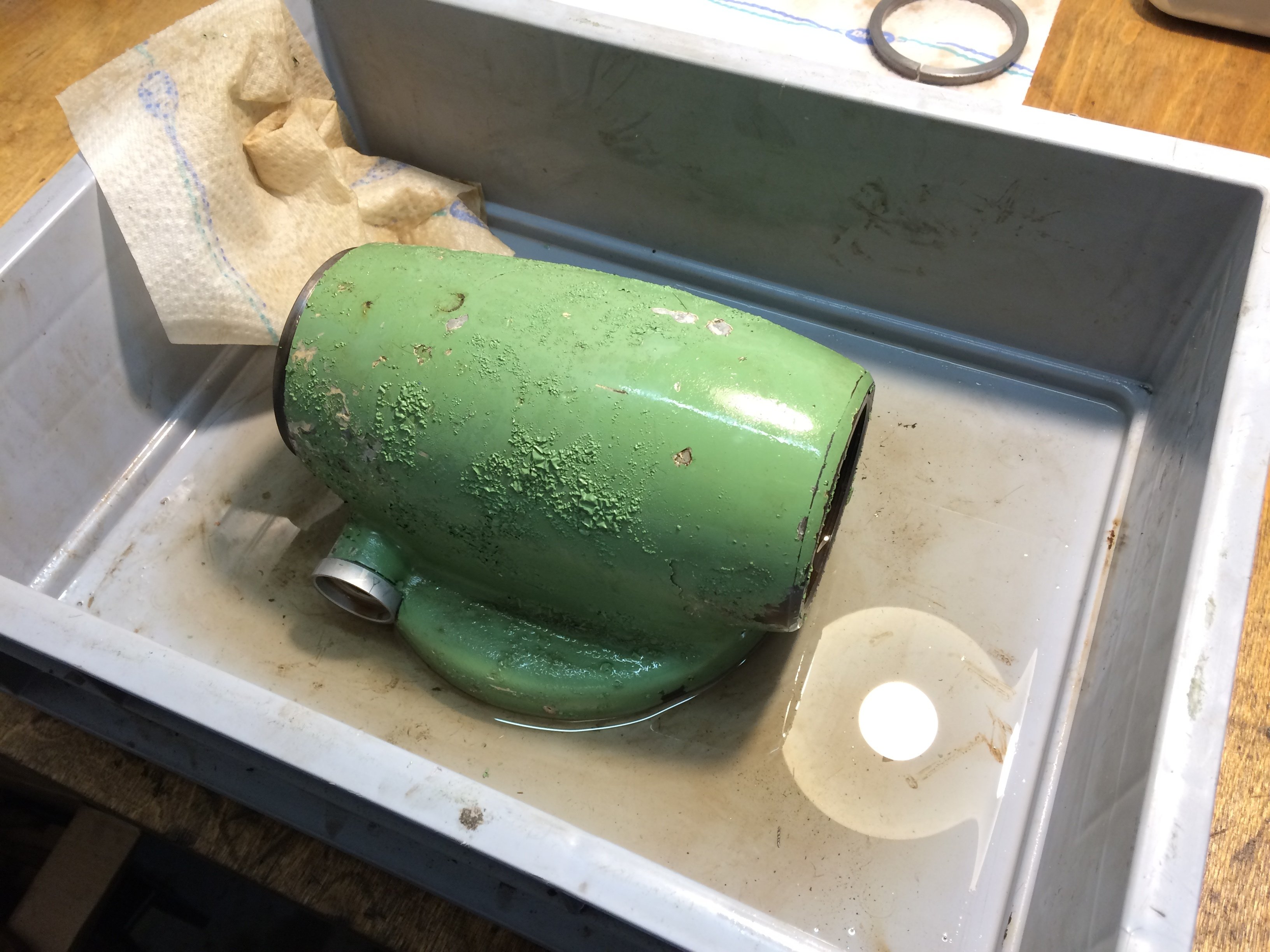
The quill housing / angle piece needed a bath in nitro thinner to peel off a layer of cheap paint:
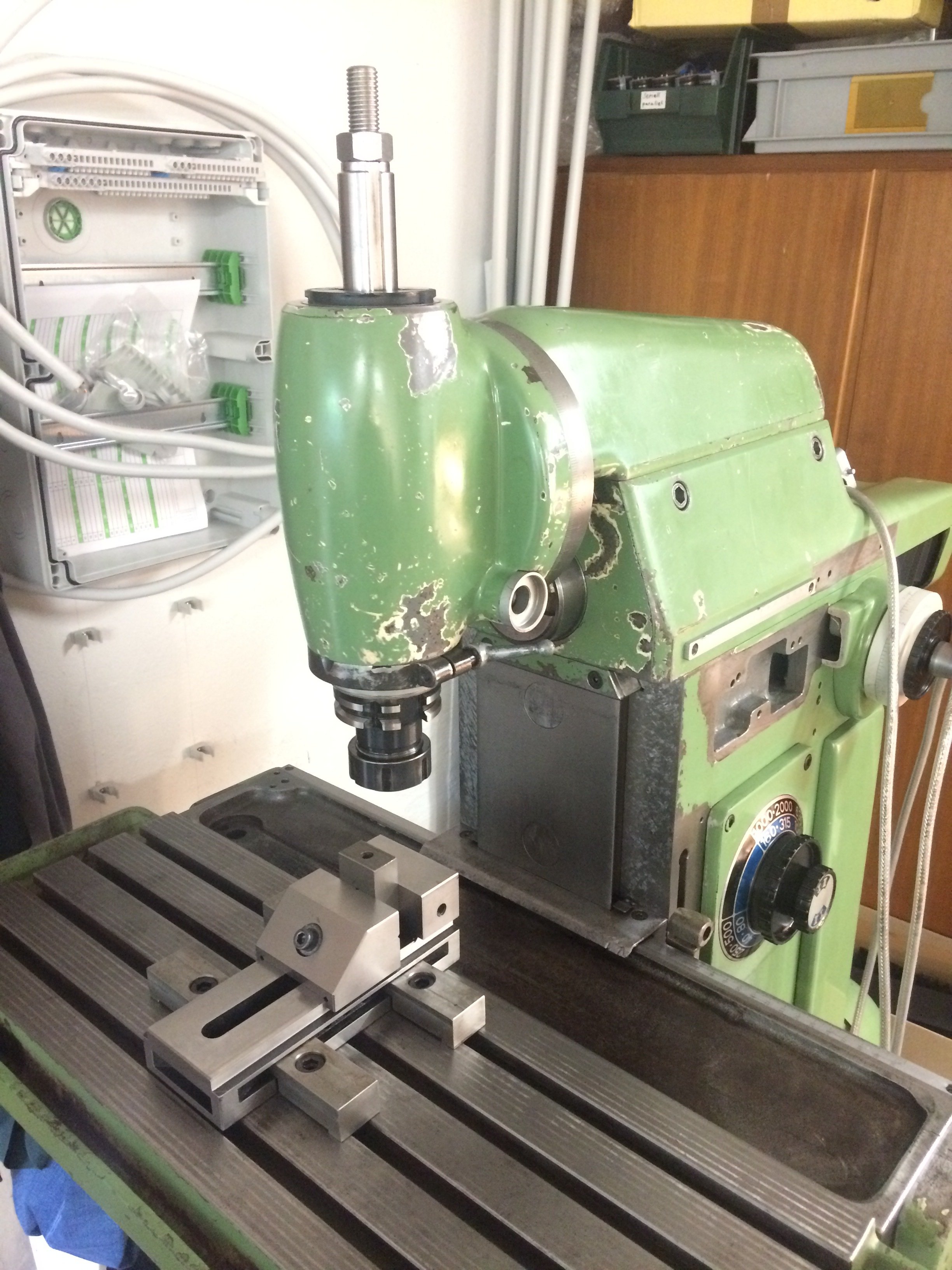
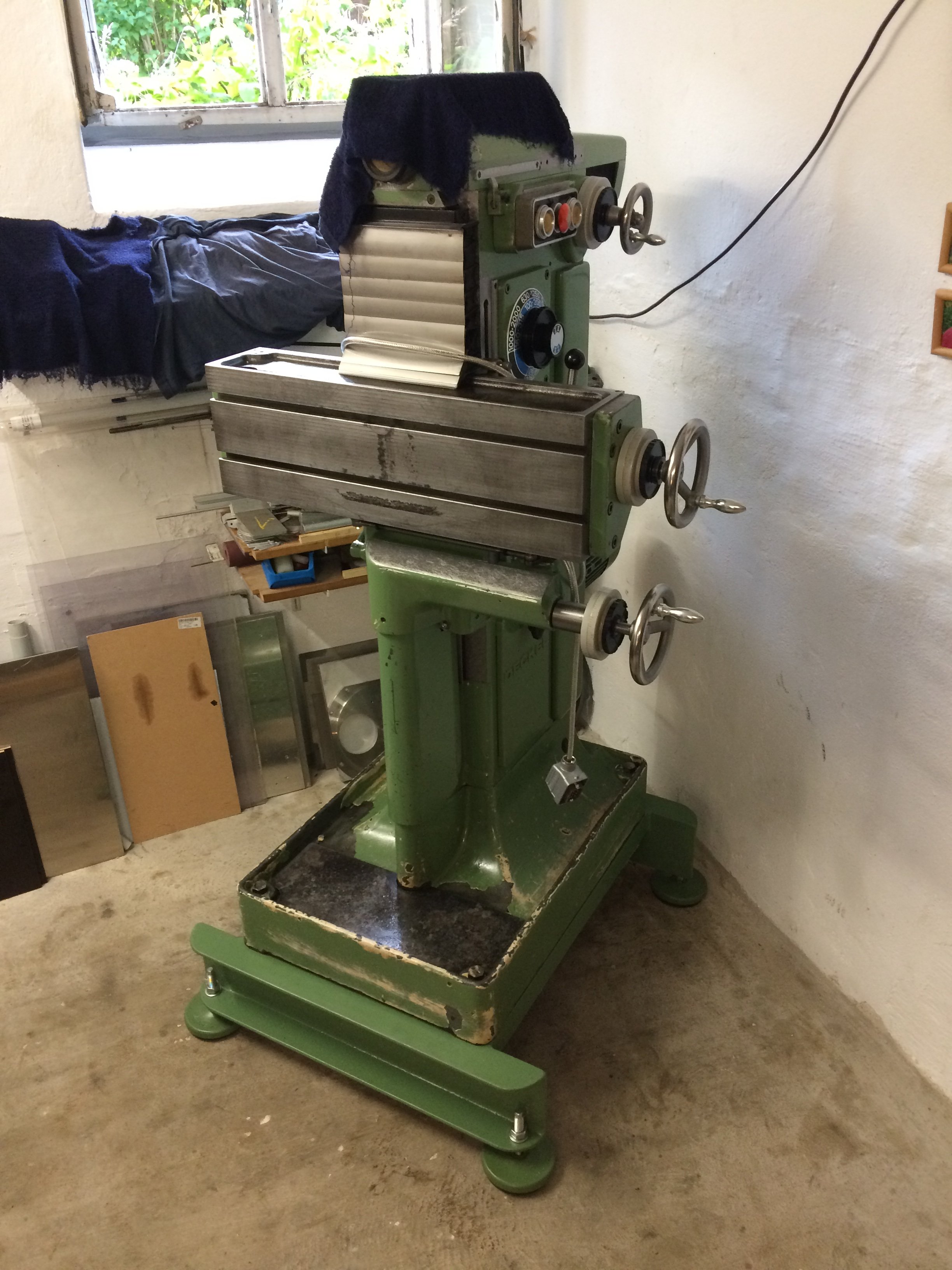
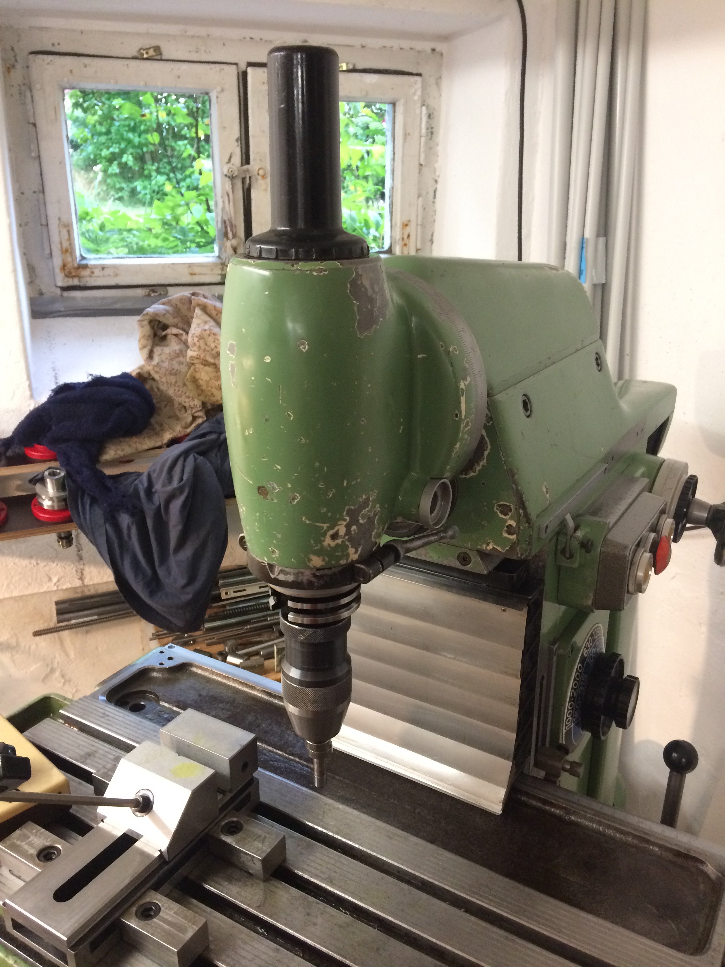
After mounting it, the FP1 is operational again:
To close out this report, a picture of me during the pre-cleaning of the subassemblies. Sometimes dirty hands (and worse…) are simply hard to avoid:

Accessories #
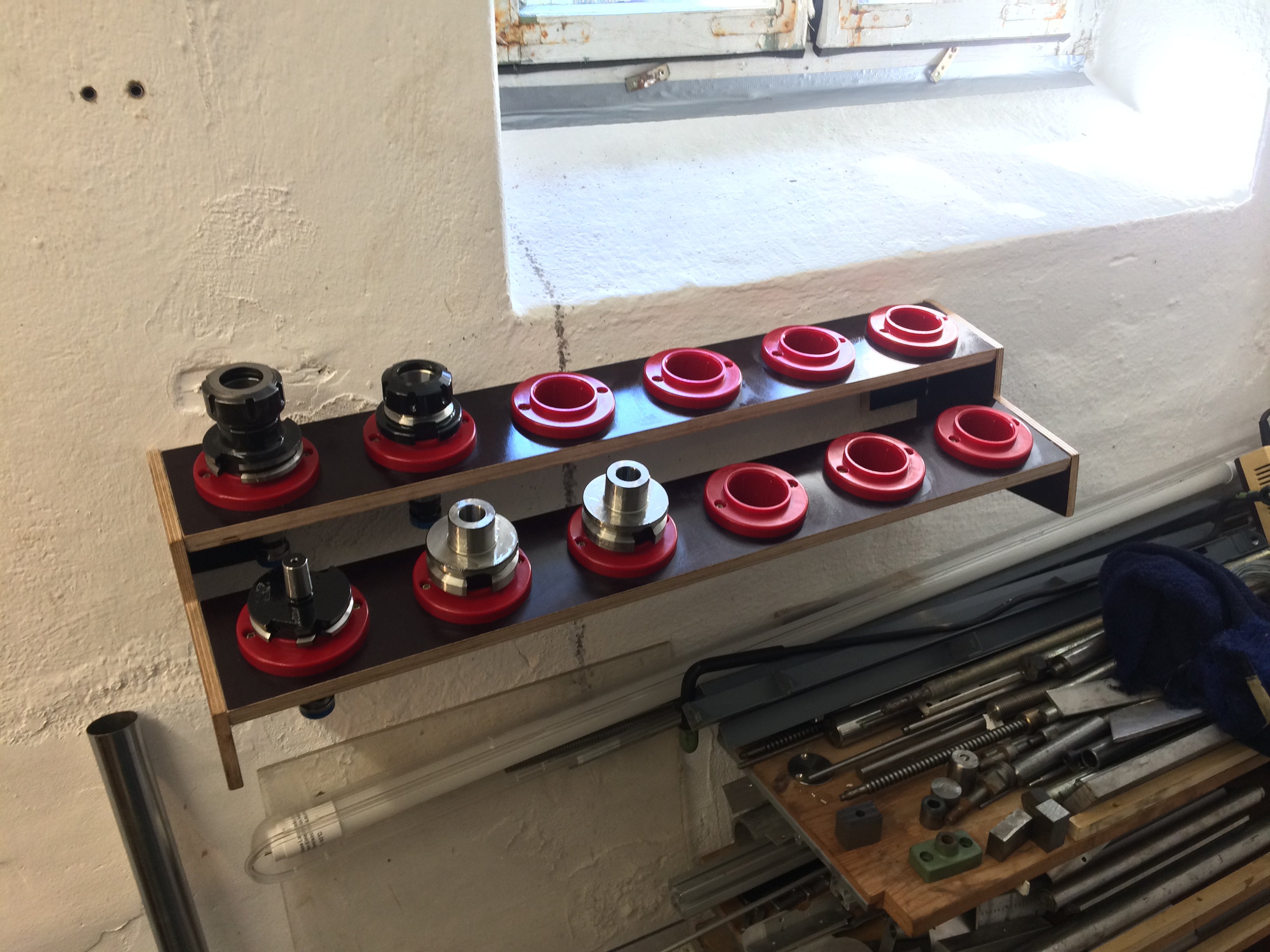
For SK40 tooling there was a row of plastic inserts available on eBay:
These were then (inspired by similar designs shown on Zerspanungsbude) fitted into a shelf:
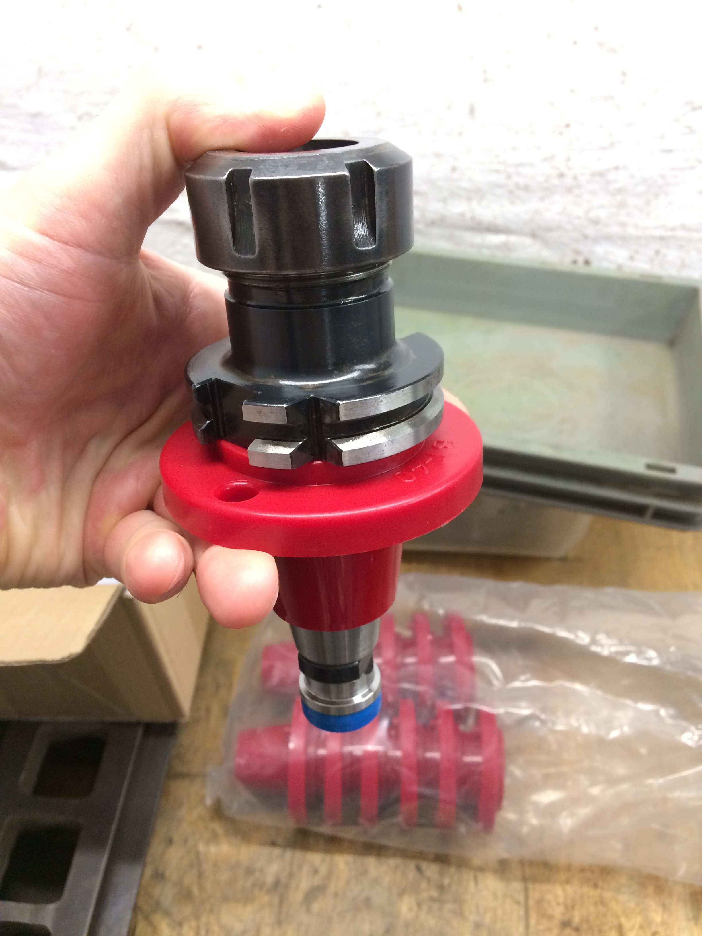
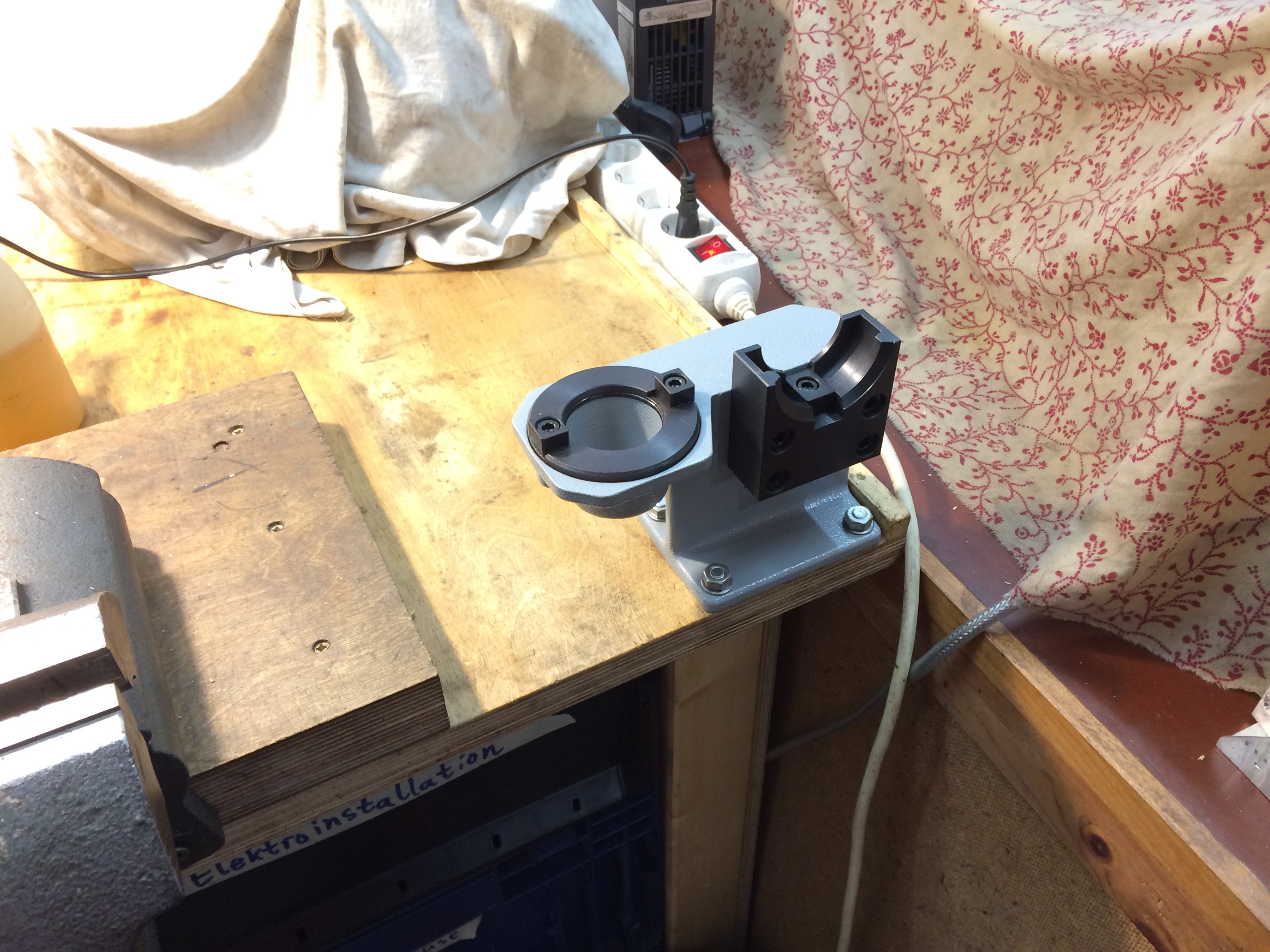
I also picked up an SK40 mounting fixture, into which collets etc. can be installed and tightened very handily. Especially with ER32 holders, which need to be cranked down quite firmly, I prefer this to doing it directly in the machine spindle.
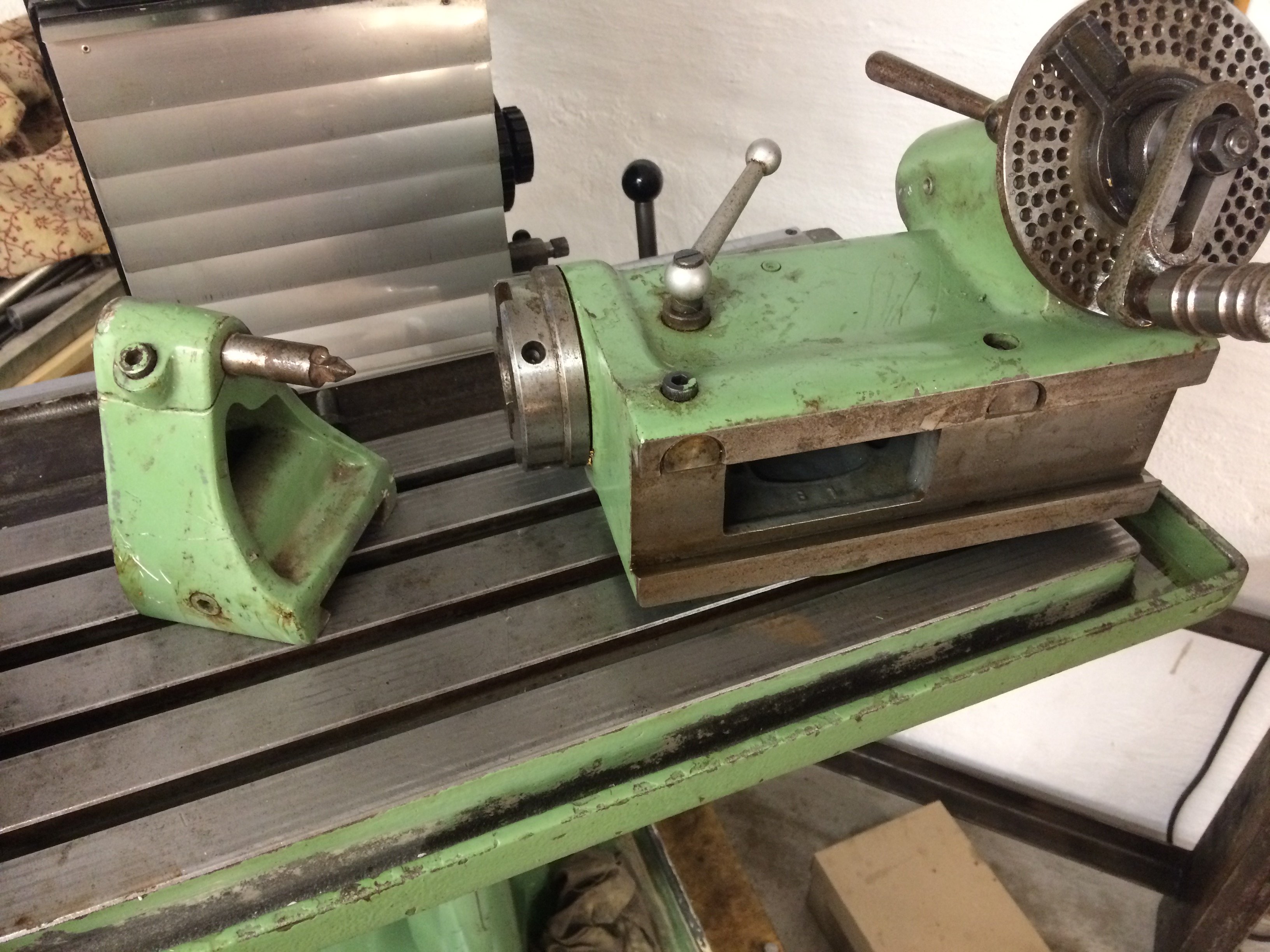
I was also able to grab an SK40 dividing head with tail support (not in the picture) and a centre, but without a mounting bracket, at a good price. A thorough cleaning is still due there. The mounting bracket I’ll probably build as a steel weldment and put on a spare vise swivel base.
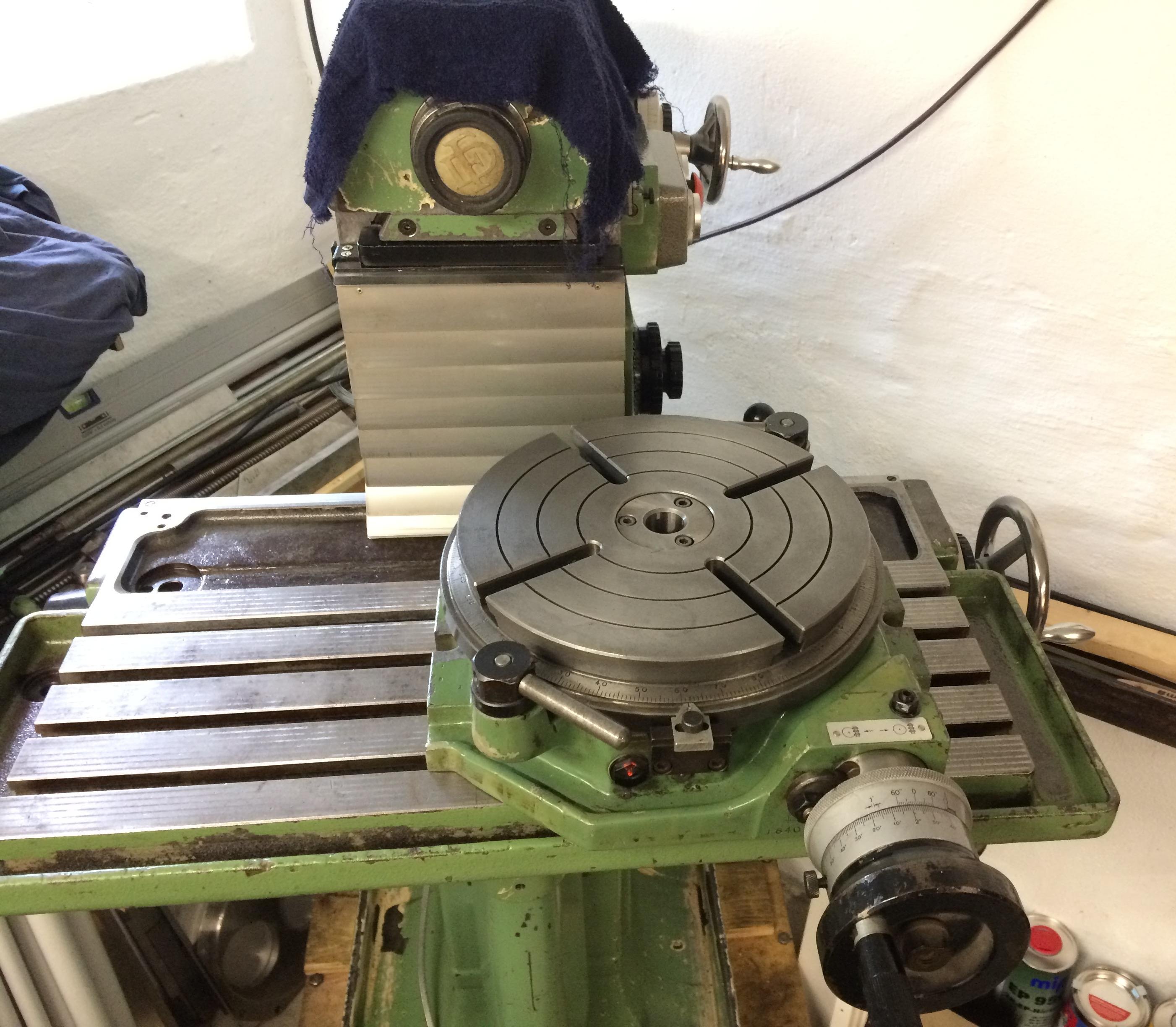
A 250 mm rotary table has also recently graced my workshop. Admittedly it’s a hefty thing on the FP1’s table, but at least it’s still smaller than the 380 mm monster from Deckel. Here too: take it apart, clean the parts and reassemble freshly oiled -> stay tuned…
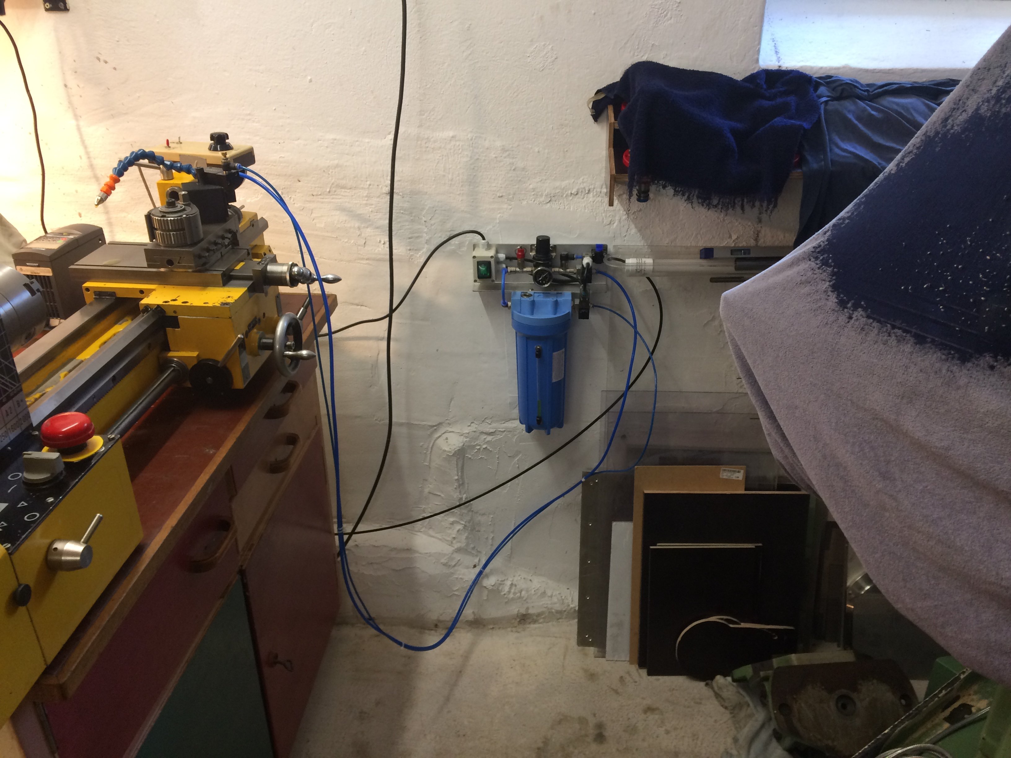
That ruled out any more excuses to keep the minimum-quantity lubrication unit floating around loose any longer. It was therefore mounted to the wall and is now available for both the lathe and the milling machine.
Stand #
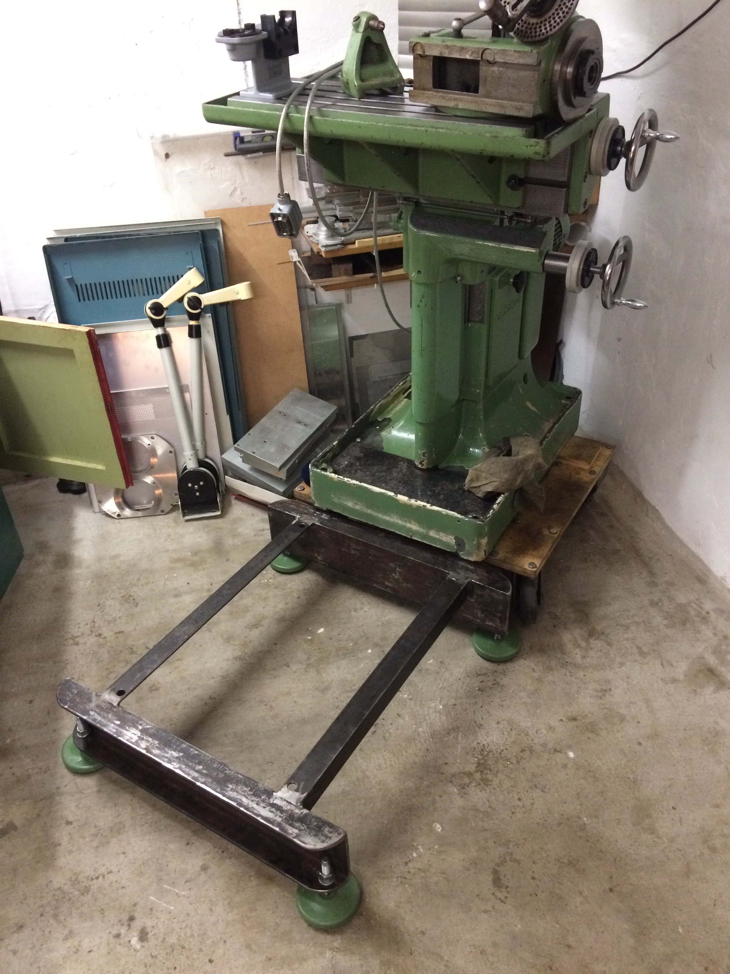
A stand for the FP1, so it can later be moved with a pallet truck and to bring the controls to a comfortable height for me, had been ready for some time:
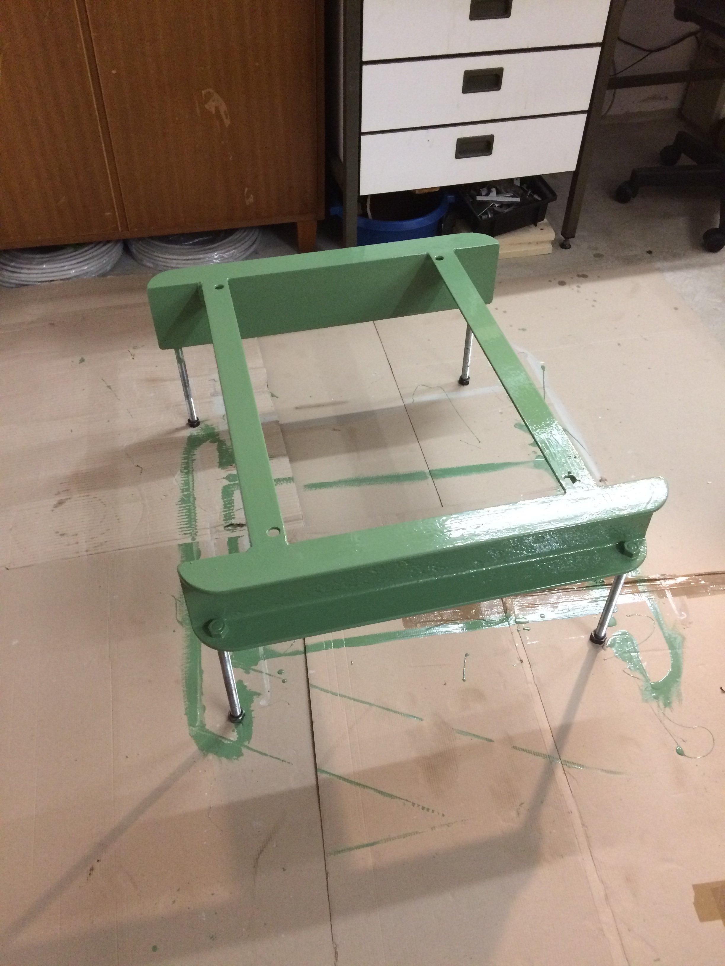
Recently it got a green coat and was ready for service:
A makeshift wooden gantry crane with a chain hoist then helped with moving the machine:
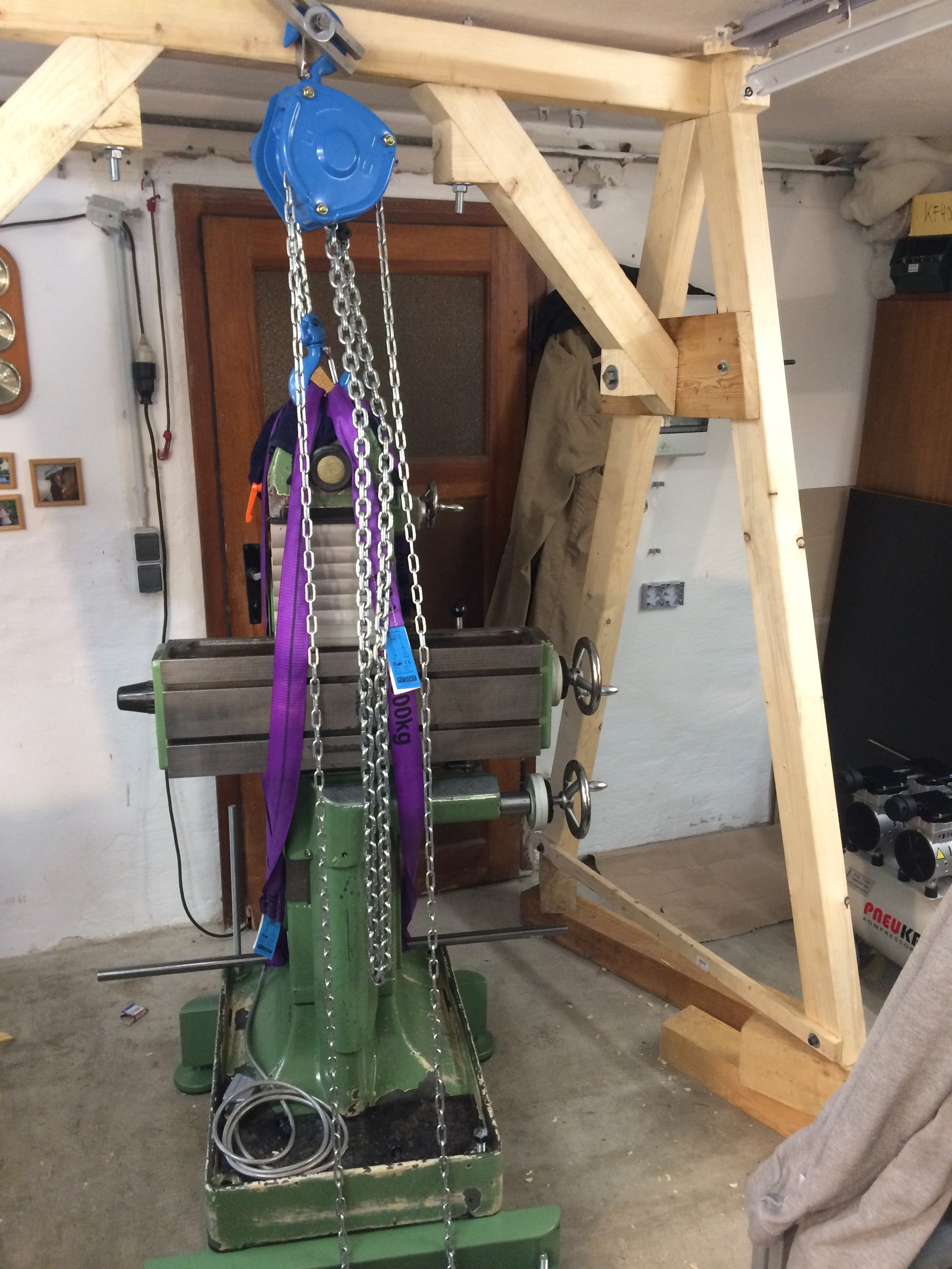
That looks a lot more civilised than a roller dolly:
Drawbar #
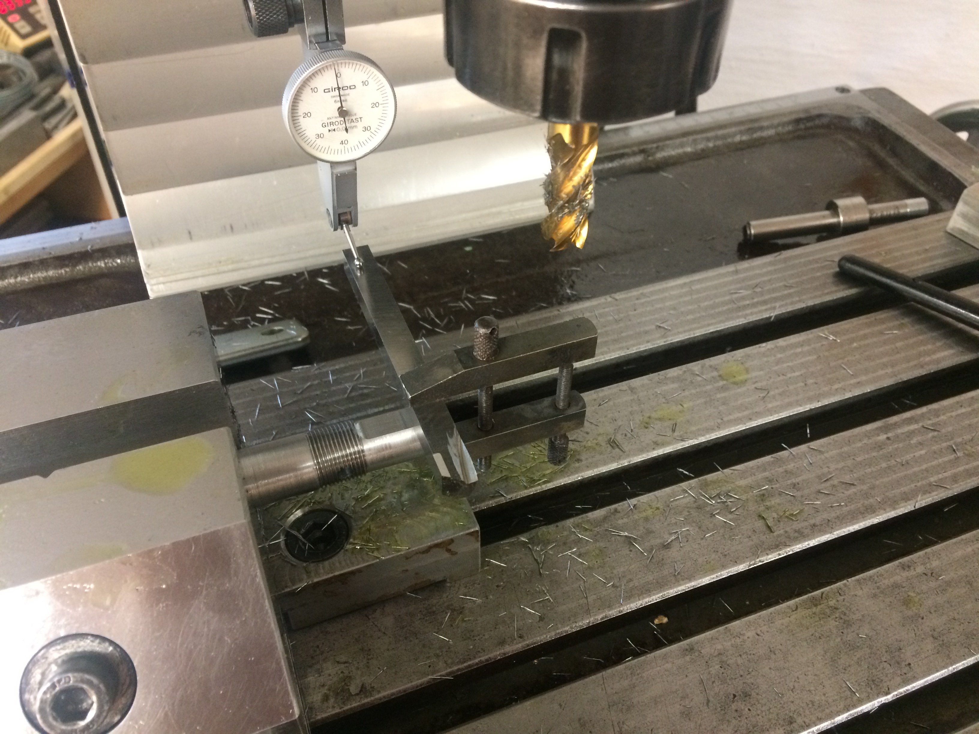
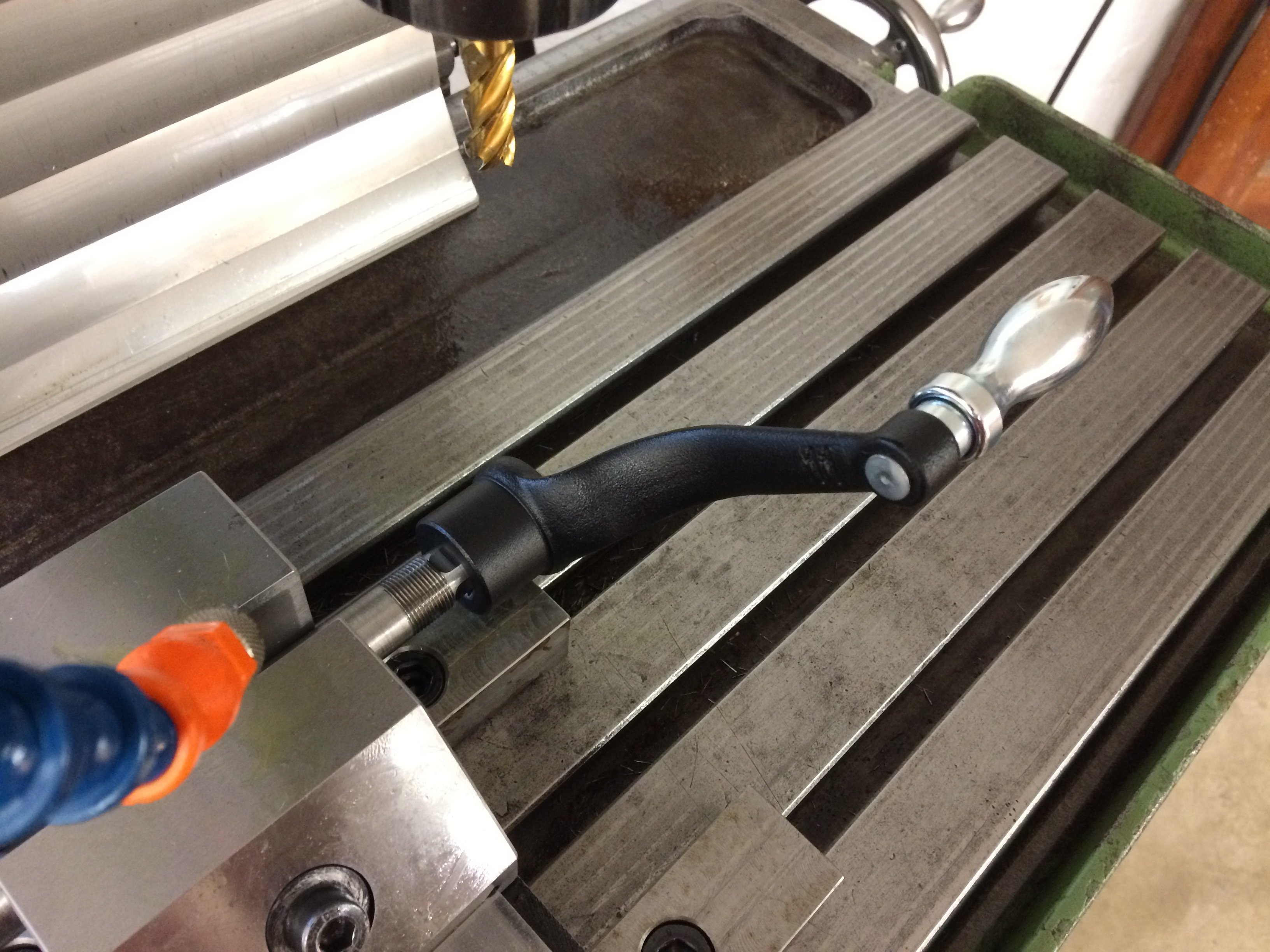
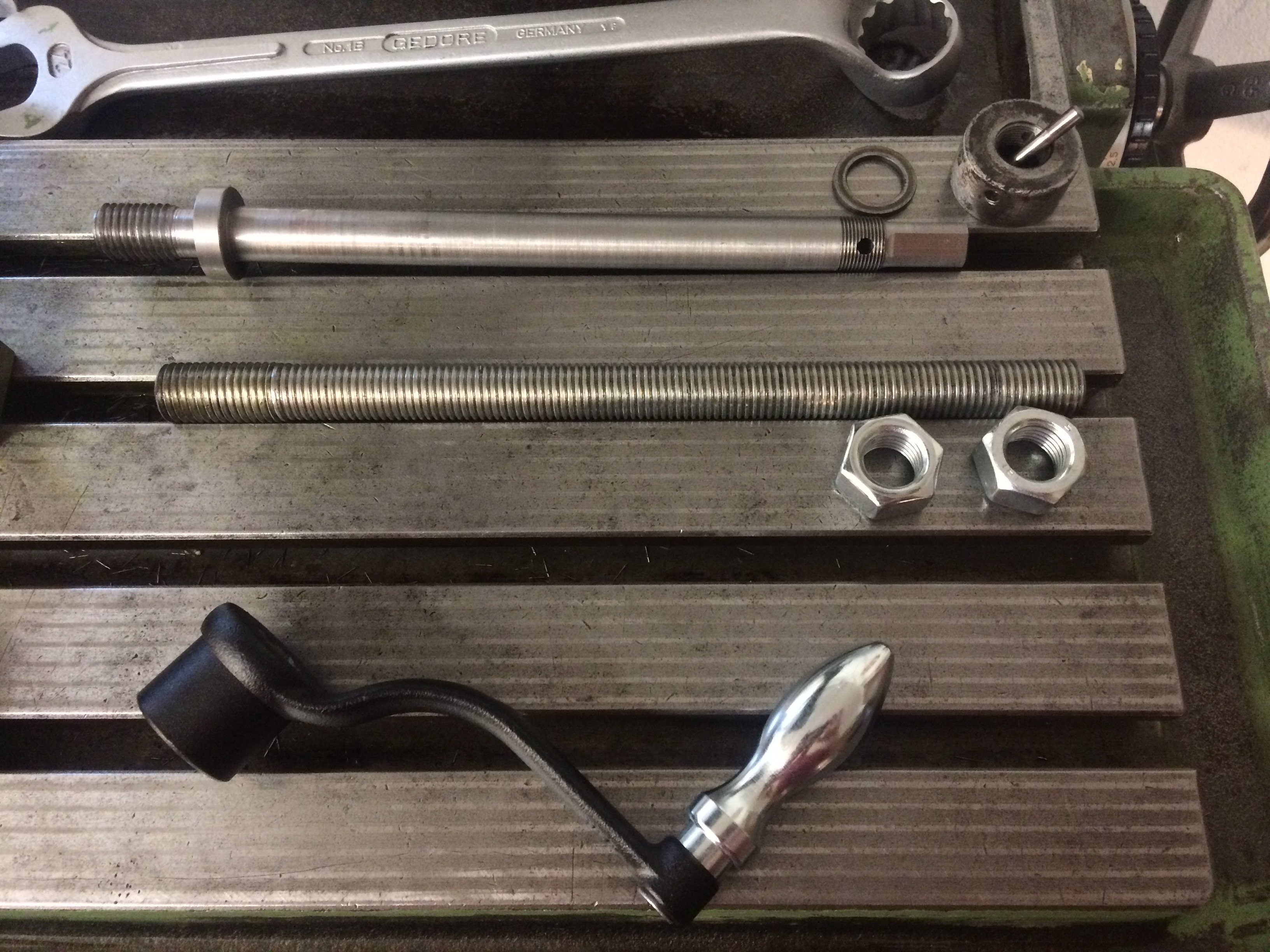
To round things off, a new drawbar with an M16 external thread (instead of the original S20x2 internal thread) has just been finished. Here while being aligned to mill the last wrench flats for a square wrench:
Fits as expected:
And here’s the drawbar in full; together with a stand-in made from M16 threaded rod. The bore in the vertical quill has a diameter of 15 mm. The threaded rod therefore had to be turned down to 15 mm over most of its length. For the lock nuts at the top there was just enough “thread depth” left. I don’t have a single S20x2 tool in the house, so I had to go with M16 from the start.
When fitted, of course, you don’t see any of this any more, but at least it’s another big step forward for the mill:
Electrical cabinet #
The electrical cabinet essentially contains a contactor control for the Dahlander motor on the machine, plus the motor of the high-speed head. There is also originally a 380 V -> 220 V control transformer so that no neutral conductor is required. Finally, there is a socket for the centring microscope, which prevents the motor from starting while a plug is inserted.
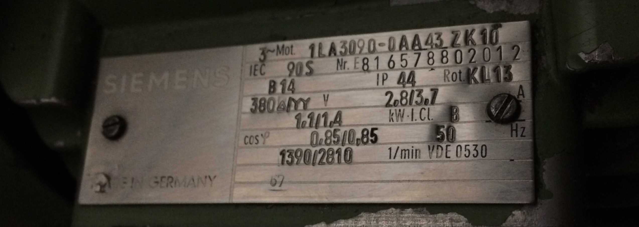
The original electrical cabinet wasn’t included with my machine, so I omitted the parts I don’t need. The motor, as mentioned, is a Dahlander with 1400 / 2800 rpm:
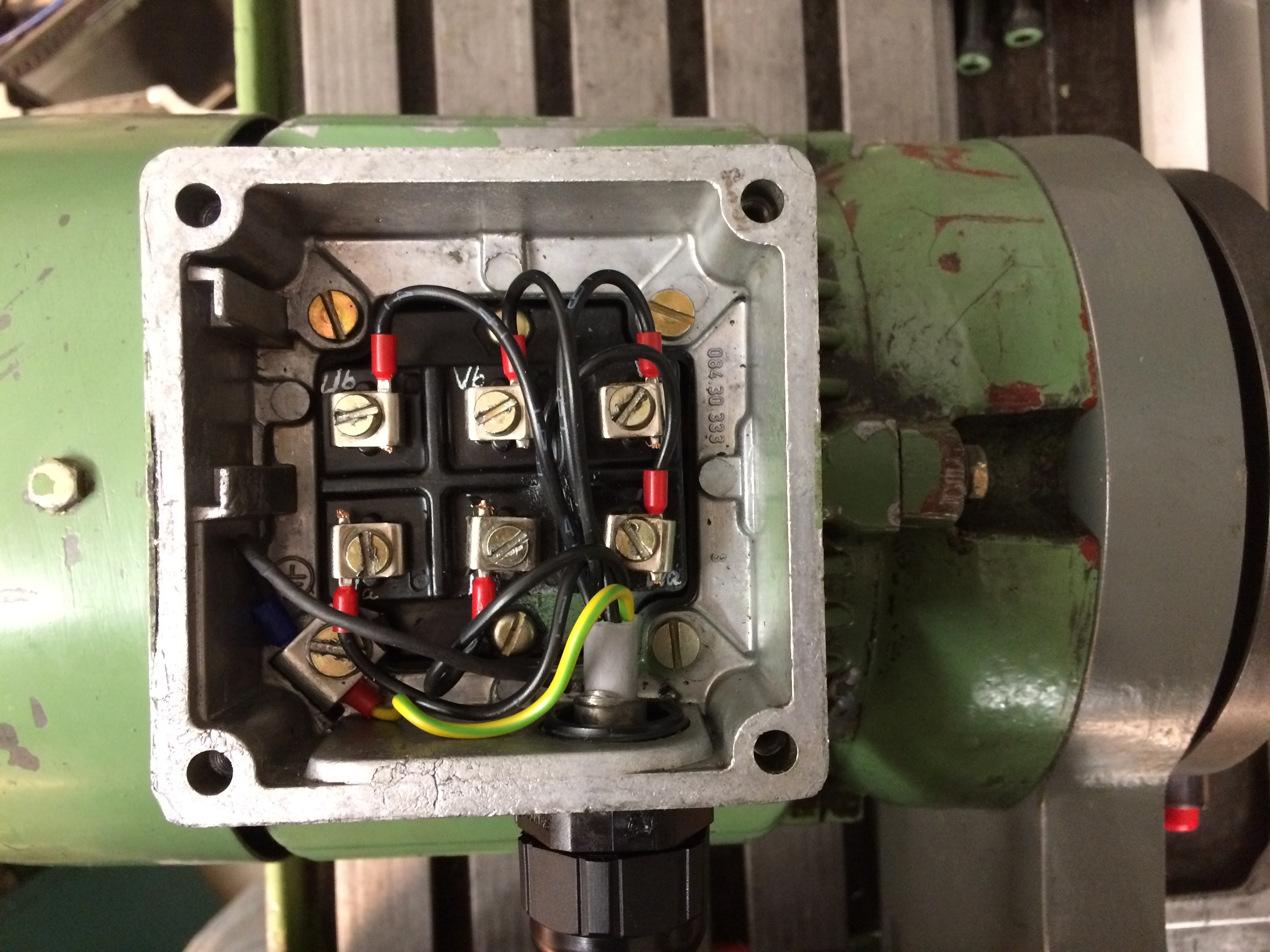
The motor connects to the cabinet via a six-conductor (+ earth) shielded cable:
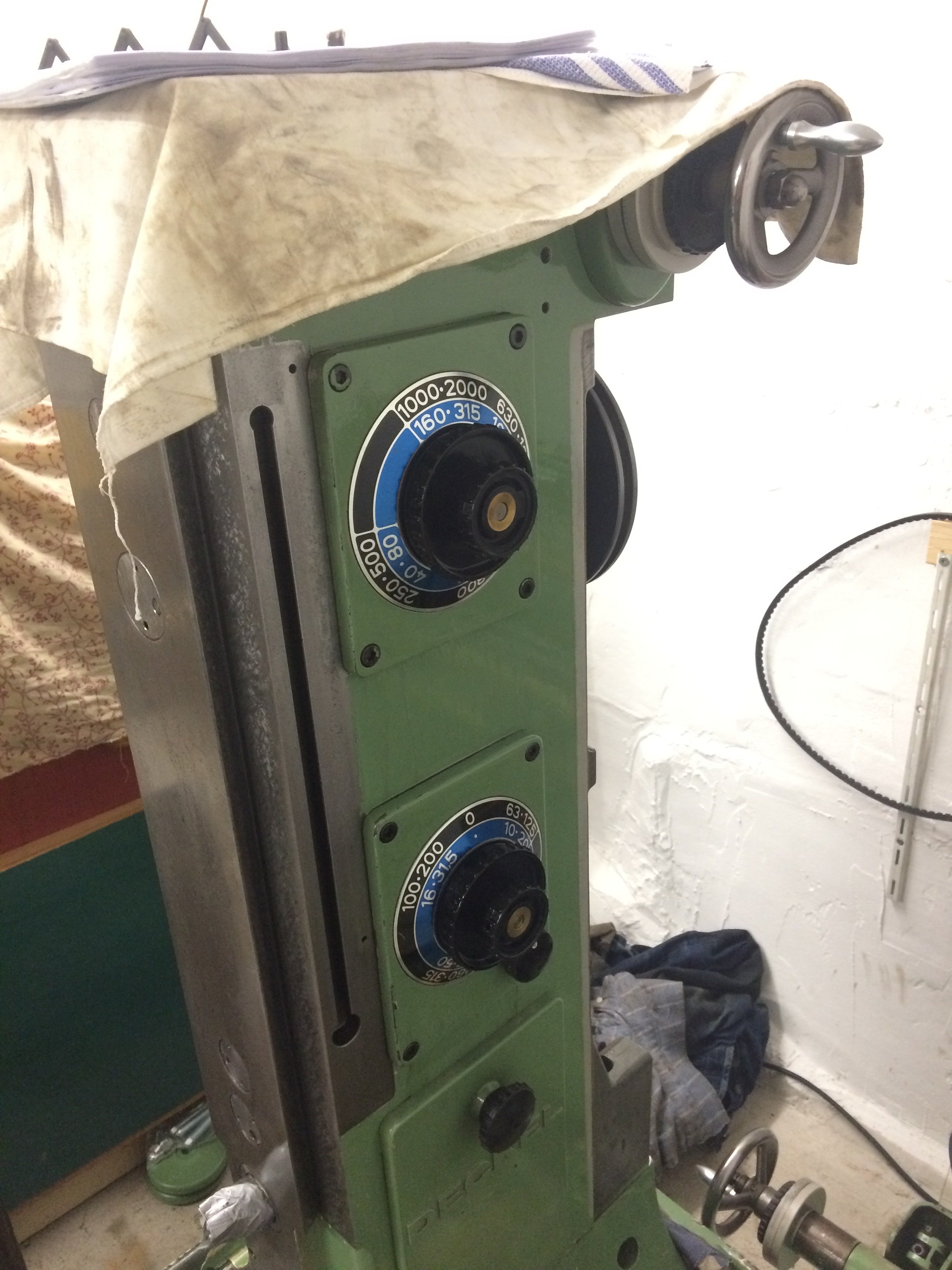
Starting from a 1960s Deckel wiring diagram and the Eaton schematic manual, I drew up the following circuit.
First the power section:
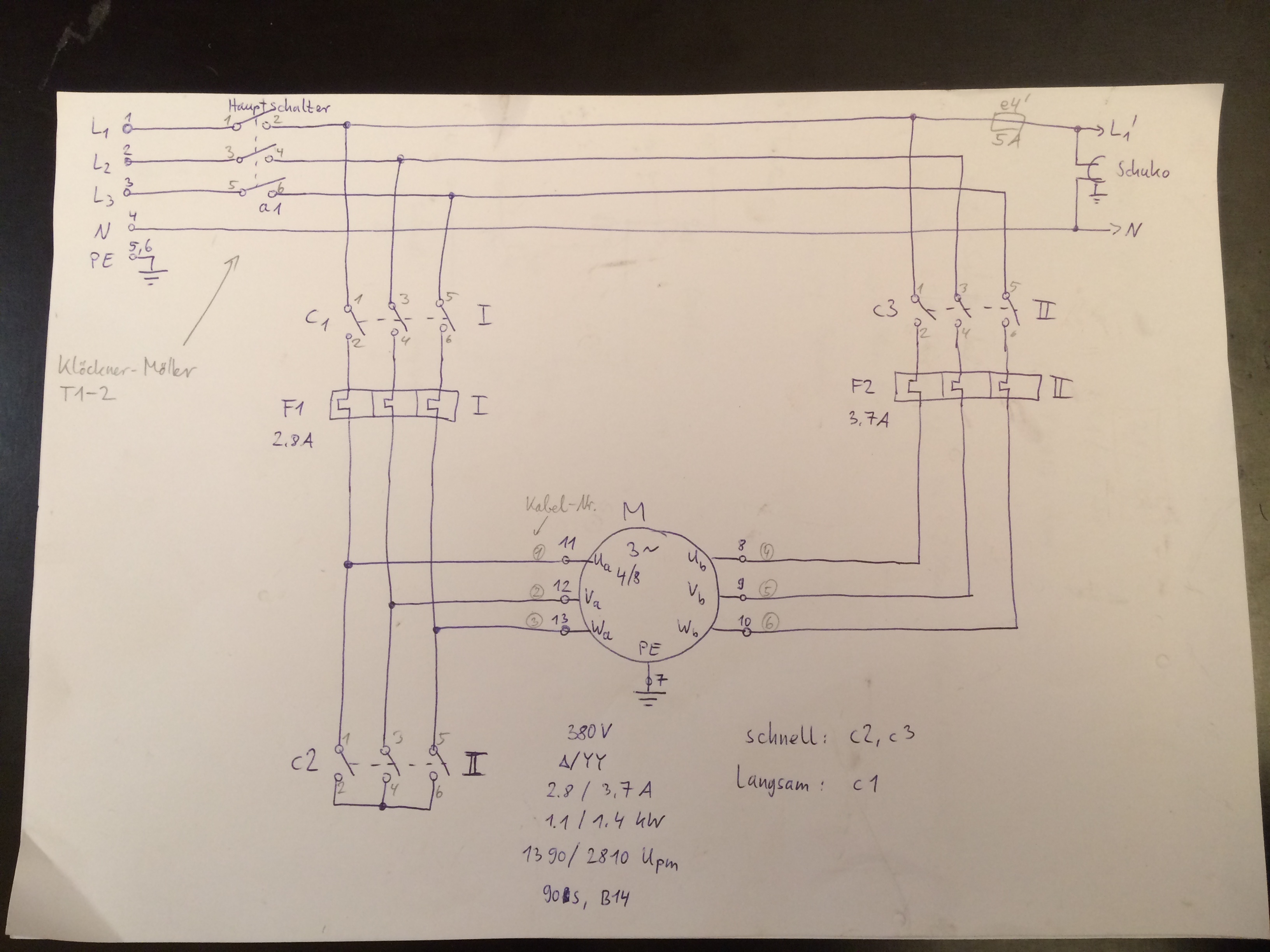
The main switch isolates the entire setup from the mains. For the slow speed, the three phases must be applied to Ua, Va and Wa. This is done via contactor c1. At slow speed, motor protection switch F1 protects against overload. For the high speed, the three phases must be applied to Ub, Vb and Wb. This is done via contactor c3. Furthermore, Ua, Va and Wa must be connected together – here via contactor c2. At high speed, motor protection switch F2 protects against overload. A Schuko socket is also switched together with the main switch and can be used e.g. for a lamp. The socket is fused via fuse e4'.
Then the control section:
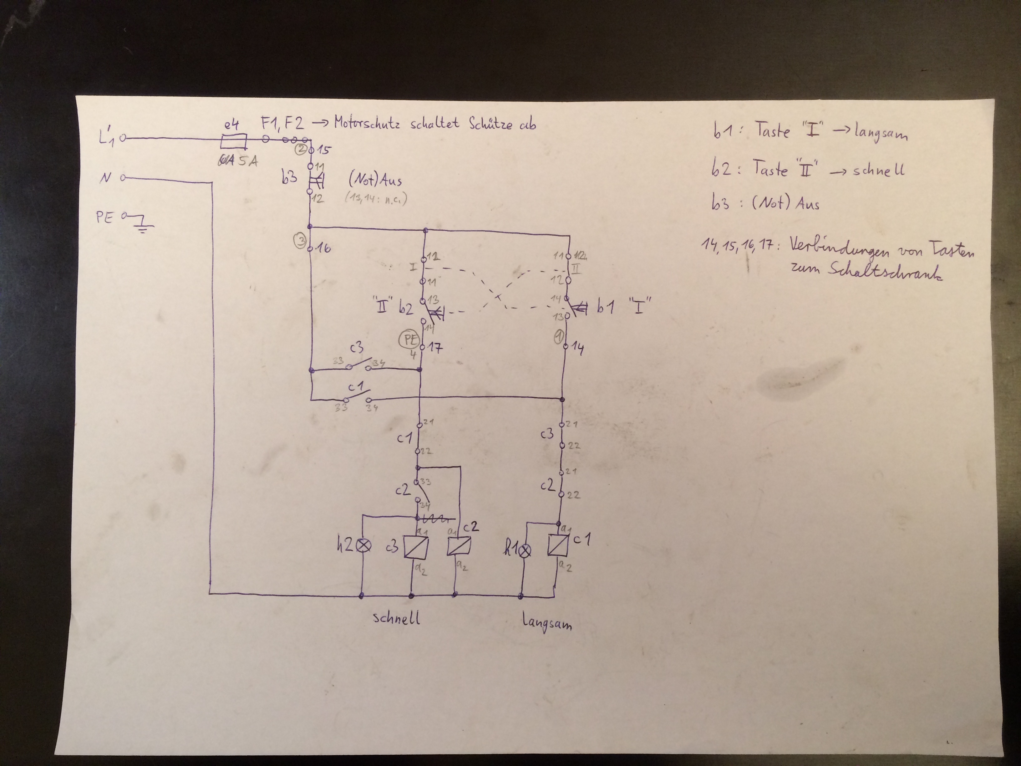
The control section uses the neutral here, since all three-phase outlets in my workshop have one. The pushbutton unit at the top of the machine is connected to the cabinet via a four-conductor control cable. The control section is fused separately, here via fuse e4. Power to the contactor coils is interrupted globally by the (E-)stop button. Either of the two speeds can be turned on via the corresponding pushbuttons. A make control contact in c1 or c3 then provides self-hold.
Things get interesting with the interlocking between the contactors, so that if one contactor sticks no immediate short circuit occurs.
For the low speed, only c1 needs to be on. A break control contact in c1 then interrupts power to the coils of c2 and c3. The coil of c1 is in turn cut off by series-connected break control contacts of c2 and c3. So the c1 coil can only get power if both c2 and c3 are open. This in particular rules out a solid short between all three phases should c2 still be closed when c1 is switched on by pushing the button.
For the high speed, c2 is first powered directly and then, via an additional make control contact, also brings in c3. This ensures that the star bridge across c2 is securely made before power is applied to the motor via c3.
Lamps h1 and h2 can be used to indicate which speed is currently active. The background noise level in my workshop is quiet enough to hear how fast the motor is running, however. I therefore left both lamps out.
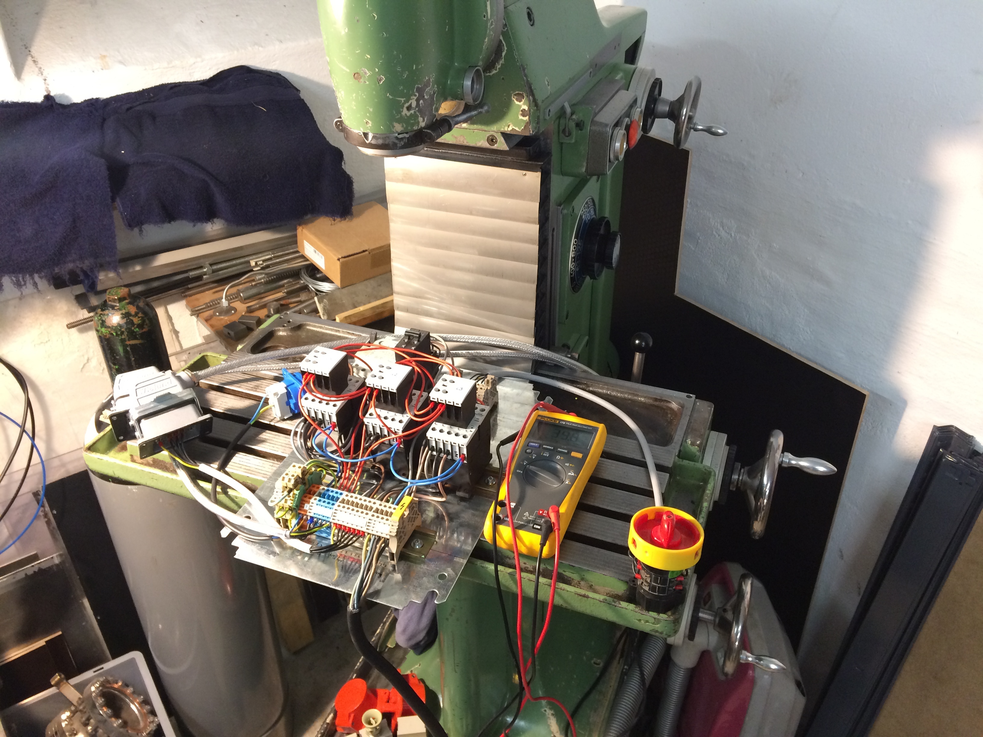
This is what the (almost) fully wired panel looks like:
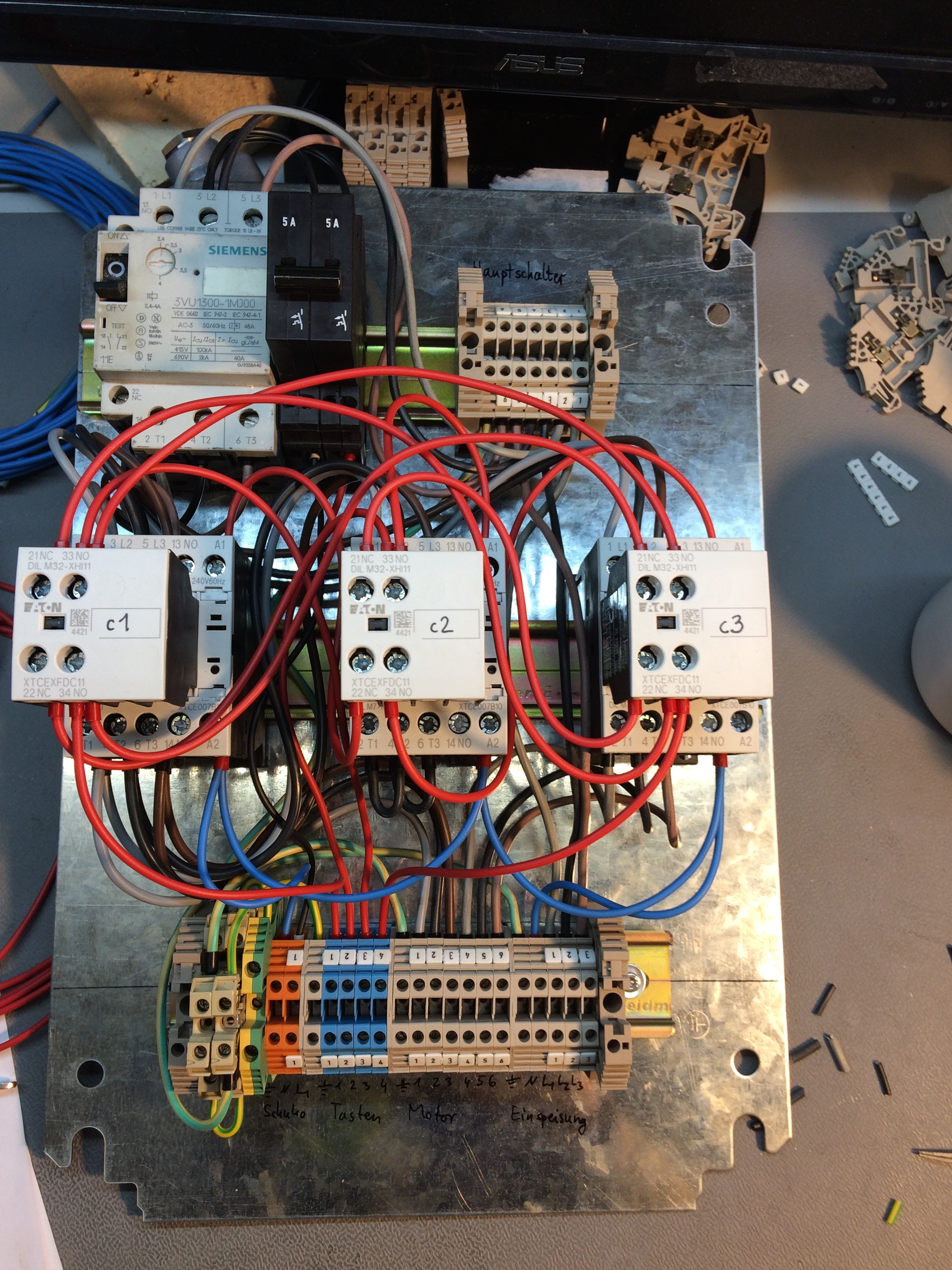
Almost, because the two motor protection switches hadn’t been delivered yet at the time of the photo. I therefore wired in an old motor protection switch directly behind the main switch as a placeholder. The two separate MPSs were delivered today, so I can post a final picture tomorrow.
Here is an overview of the parts ultimately fitted:
- 3x power contactor Eaton DIL-M7-10
- 3x auxiliary switch Eaton DIL M32-XHI11
- 2x motor protection switch Eaton PKZM0-4
- 2 m LAPP OeLFLEX(R) CLASSIC 110 CY – 7G1.0 mm^2 (motor)
- 3 m LAPP OeLFLEX(R) CLASSIC 110 CY – 4G0.75 mm^2 (buttons)
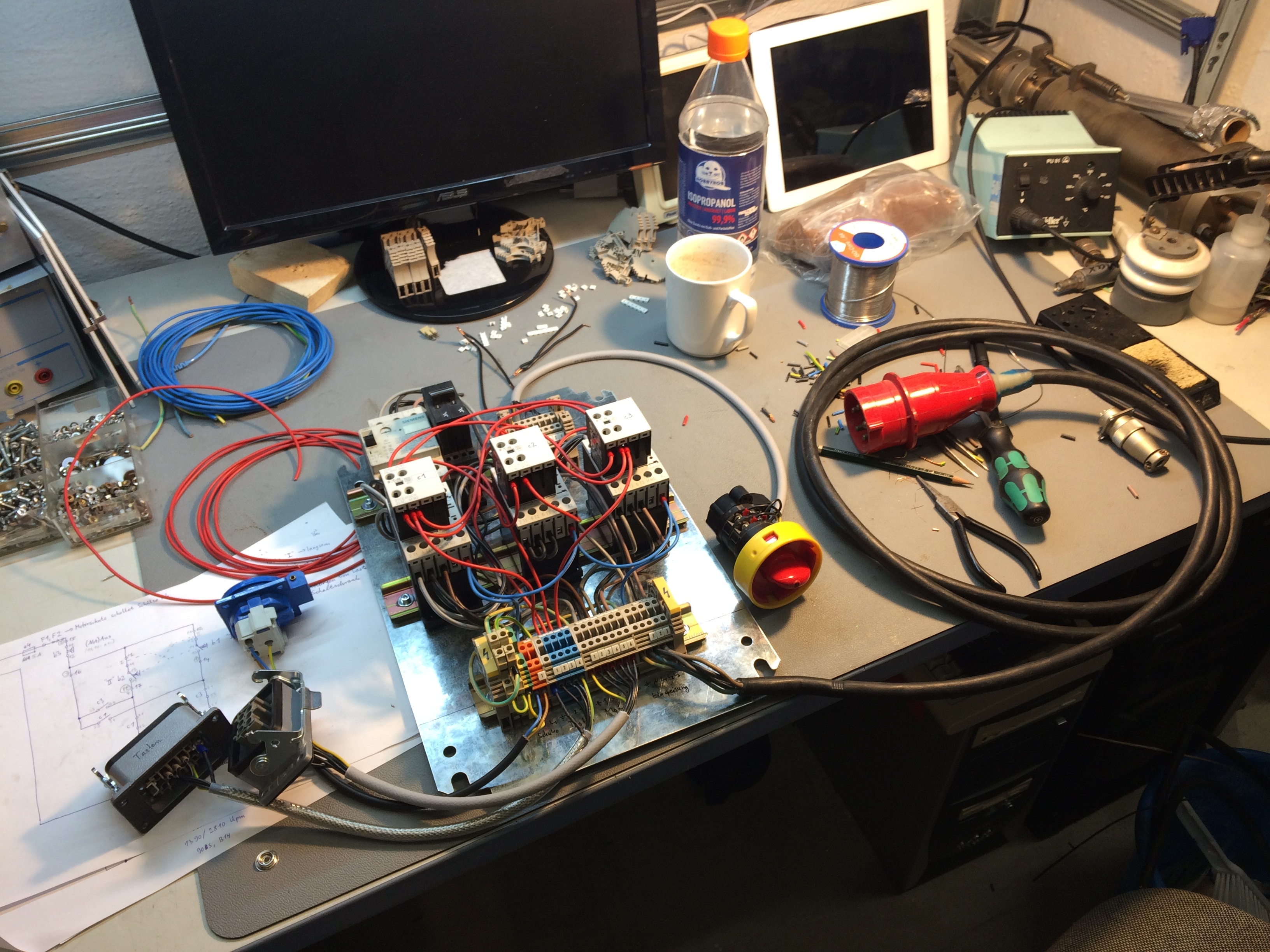
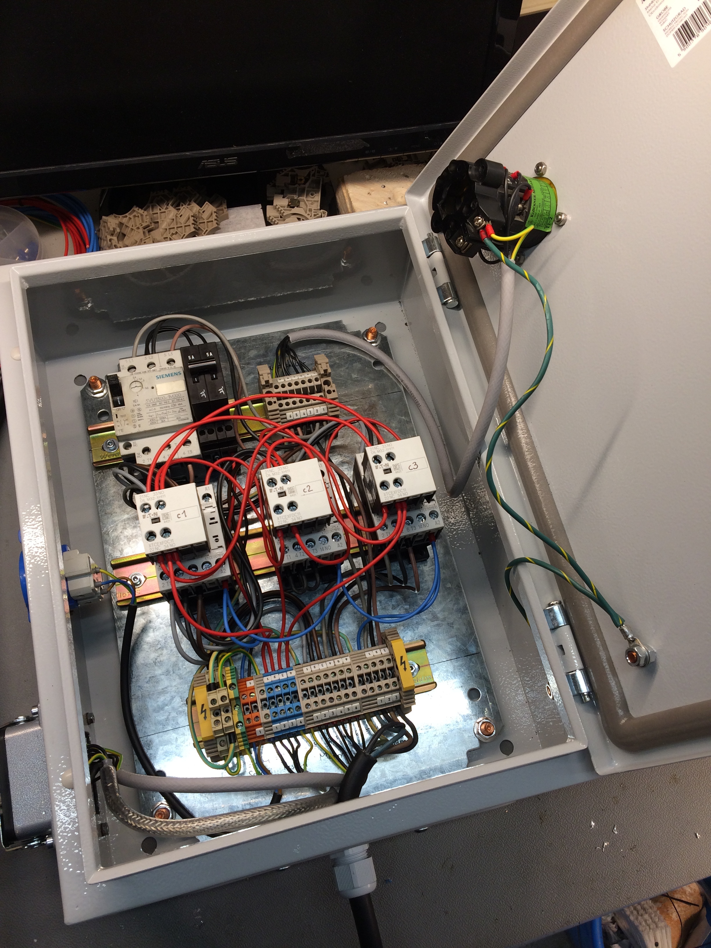
Here, then, the connectors etc. are already plugged in for testing:
A provisional commissioning showed, gratifyingly, that the circuit
works as intended and you can press the buttons in any order without
the contactors getting in each other’s way.
I therefore conclude that the interlocking circuit (as shown above)
works safely.
The whole arrangement goes into a 300x400x150 mm cabinet:
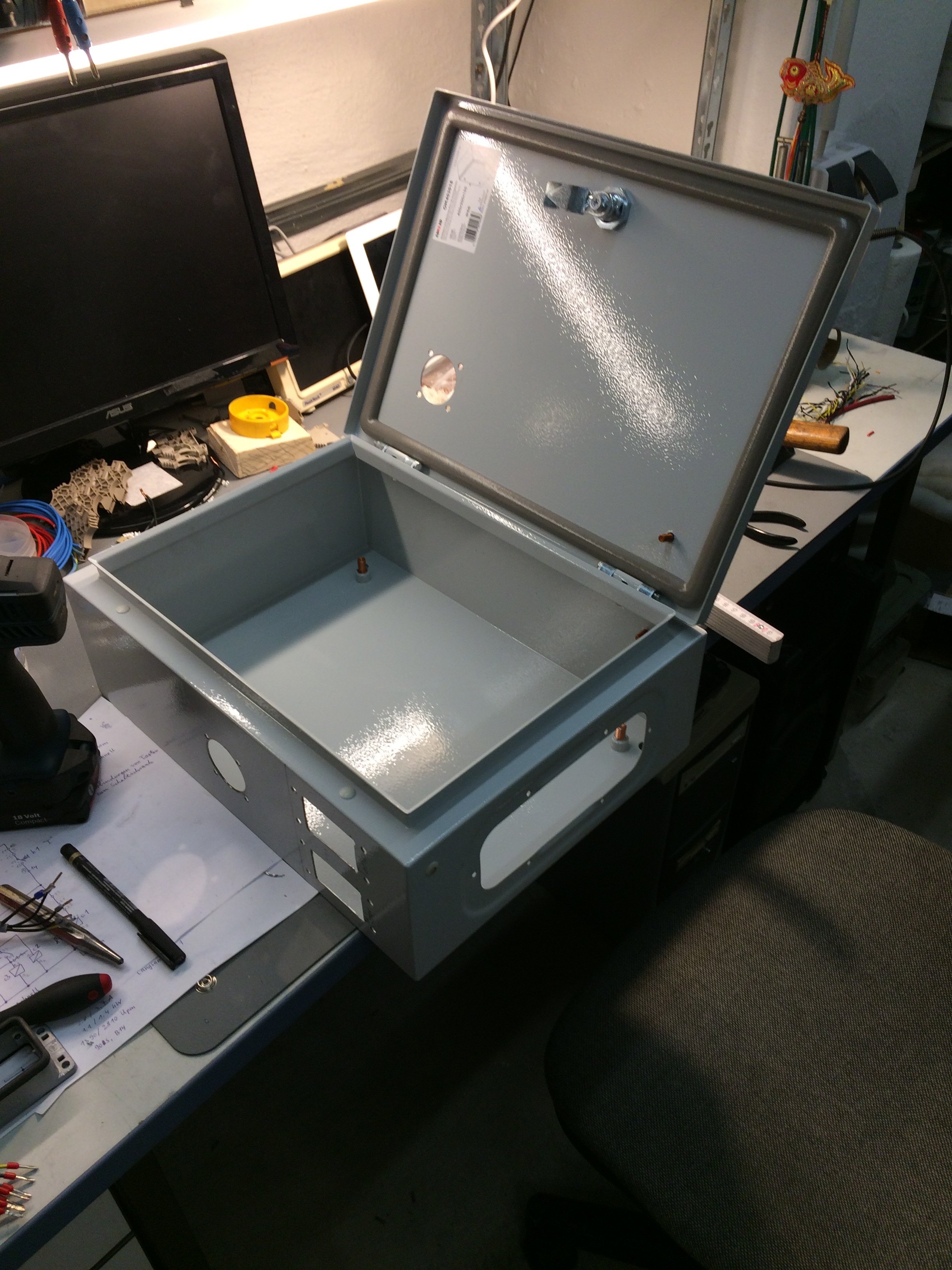
Fitting the parts wasn’t difficult any more:
There was still a good spot for the cabinet on the wall next to the
mill, so it’s hanging there now: