GYS PROTIG 201 AC/DC #
A GYS PROTIG 201 AC/DC has recently moved in with me:
I had been toying with the idea of getting a TIG welder for some time – for welding work on vacuum-system parts, for general home and workshop use, and because it’s fun to splash liquid metal around. Recently, one of my flatmates approached me – he also needed a TIG welder for an art project. The decision was quickly made; the next question, naturally, was: which one?
Picking a model #
Quite a while ago I had had my eye on the Welbach AMPERO 225, because it seemed marginally better made than the usual cheap units. Unfortunately it turned out you can’t get this one anywhere any more. While searching for an alternative – during which any number of cheap units flickered across my screen – the conclusion solidified that, in this case, it would make sense to spend a bit more than originally planned. The build quality of the cheap alternatives, especially the connectors for the torch trigger and/or the foot pedal, increasingly put me off.
I eventually struck gold at the French company GYS. I ordered the TIG 200 AC/DC HF through the online shop https://www.ach-shop.com and (after a week and several phone calls) received the PROTIG 201 AC/DC instead. Apparently the “TIG 200 AC/DC HF FV” was already a discontinued model when I ordered, but the shop hadn’t yet taken it off the catalogue. Anyway – the “PROTIG 201 AC/DC” is the designated successor, and who would object to a more modern unit at the same price…? A short overview of the most important data from the manual:
- supported processes: stick (MMA), TIG DC, TIG DC pulse, TIG AC, etc.
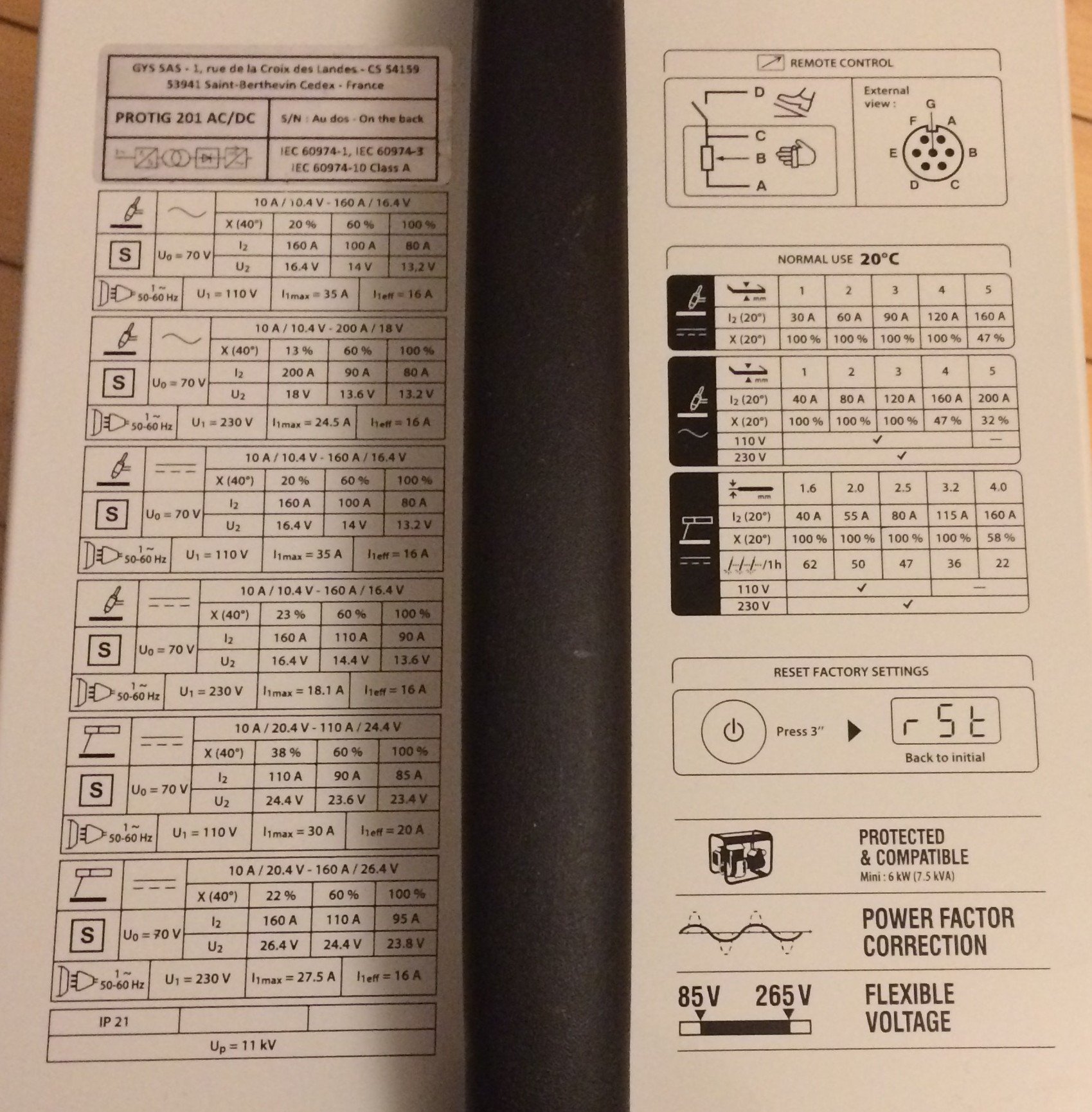
- TIG AC current: 200 A (13%), 90 A (60%), 80 A (100%)
- TIG DC current: 160 A (23%), 110 A (60%), 90 A (100%)
- MMA current: 160 A (22%), 110 A (60%), 95 A (100%) The percentages in brackets are the duty cycles.
- mains lead: 2.5 m x 1.5 mm^2 with Schuko plug
- active PFC, operates from 85 V to 265 V mains
- “Fan: when stick (MMA) welding the fan runs continuously. In TIG mode the fan only runs during welding and switches off after cool-down.”
- HF or lift start for TIG
- the pinouts of the torch trigger and the foot pedal are printed in the manual
Unboxing #
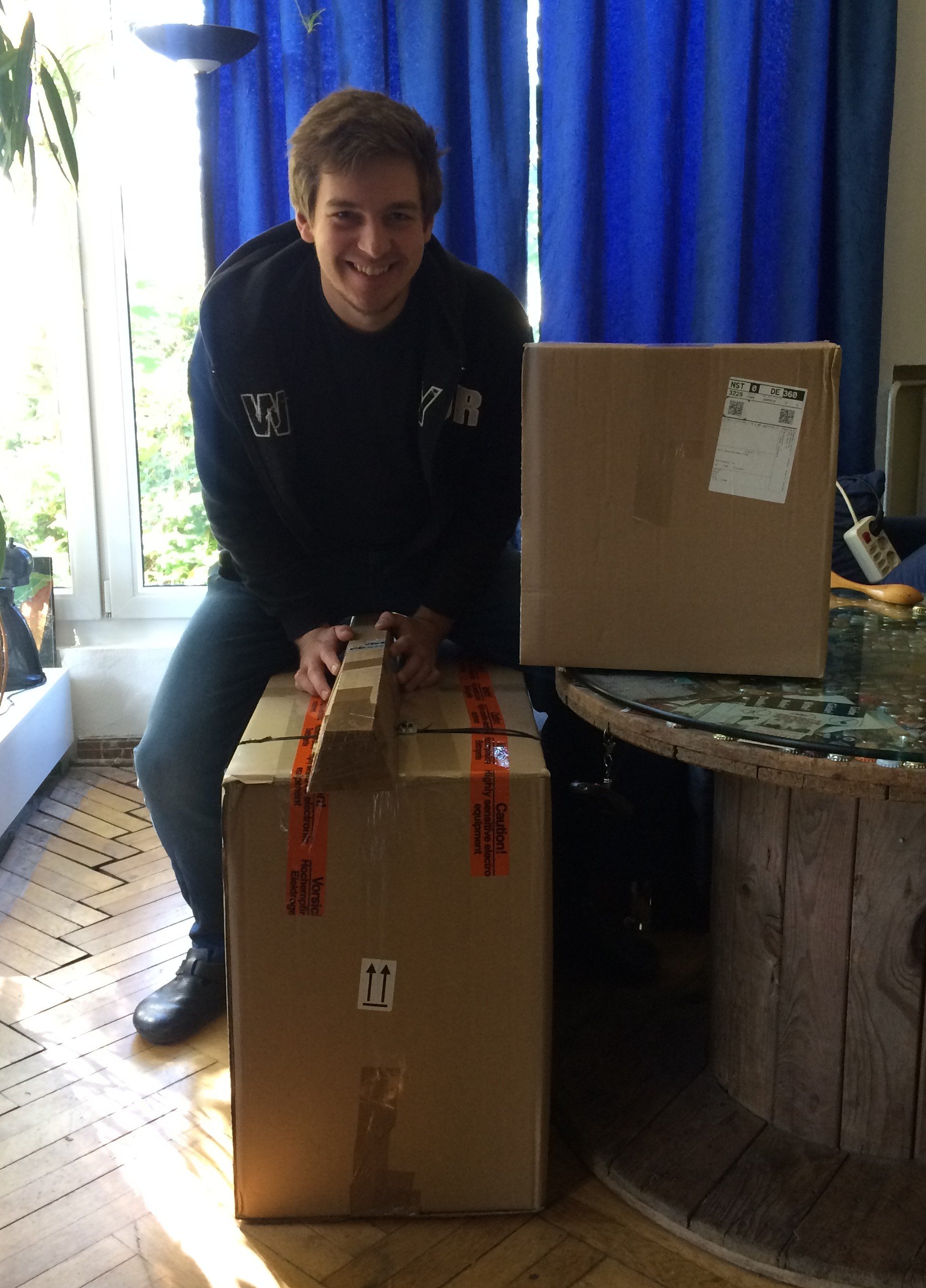
Last week the day arrived and GLS dropped off a few large parcels:
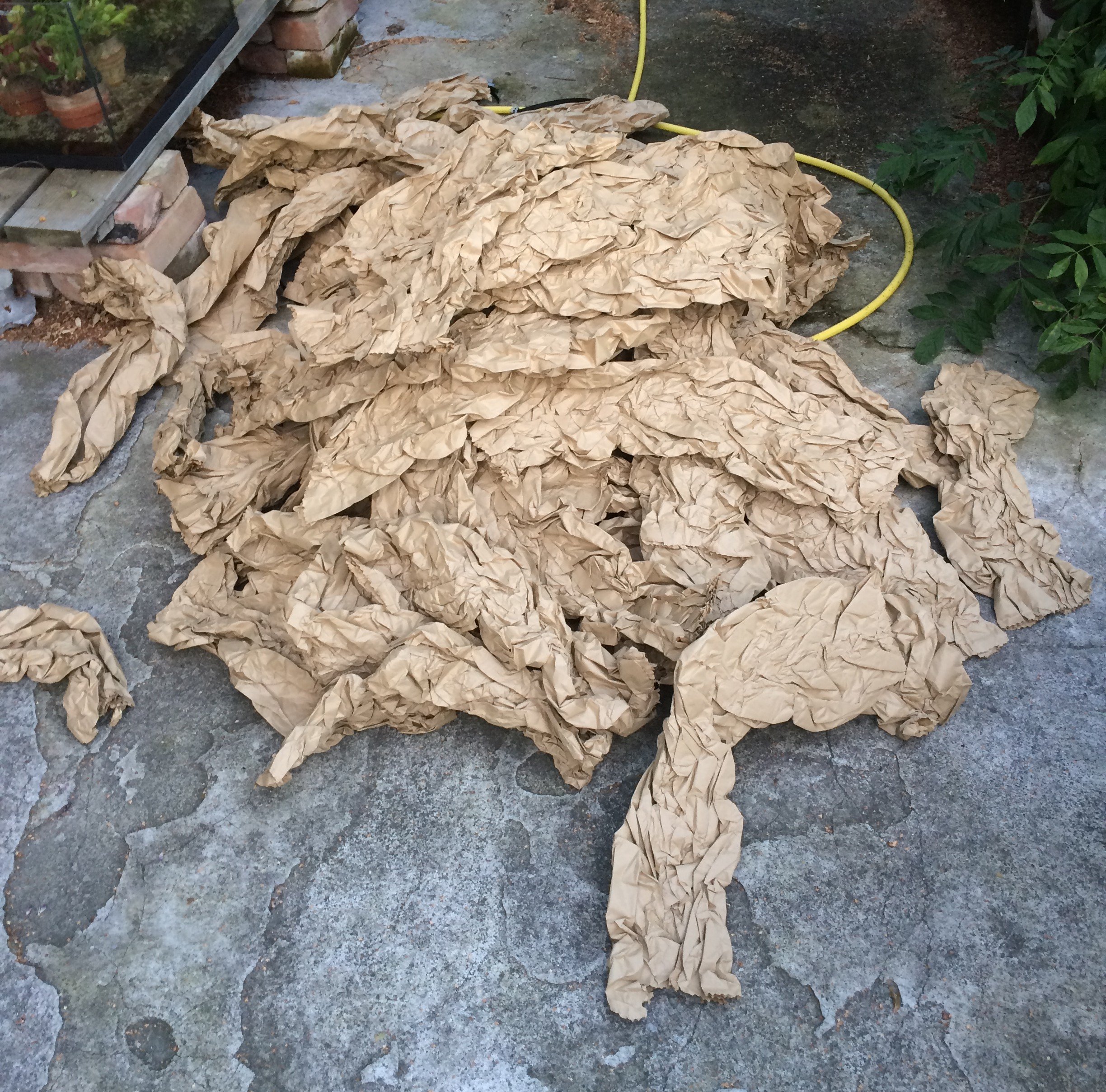
The first thing on opening was a sobering realisation: there’s just paper in here!
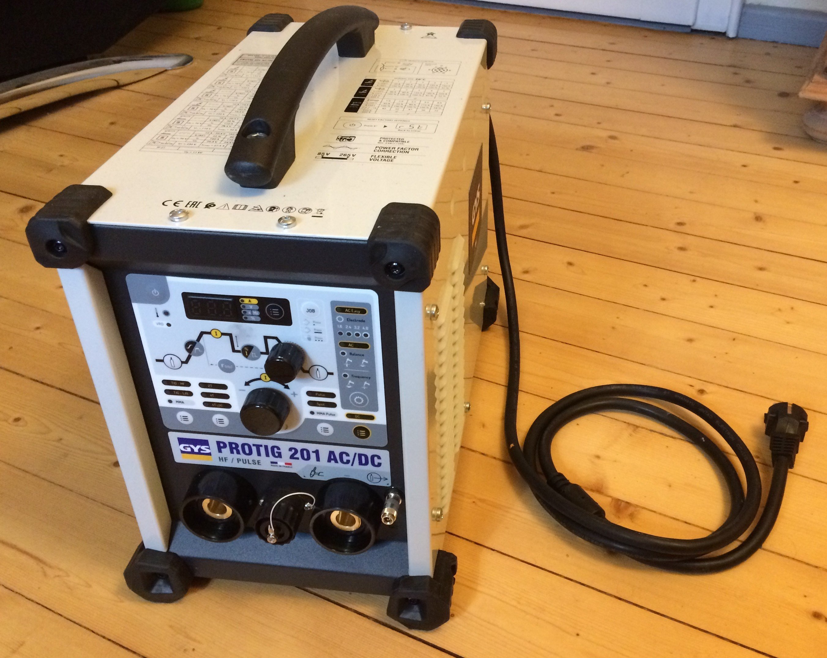
Buried in all that filler material (read: GYS packed the items properly) there was, in fact, a welder with accessories:
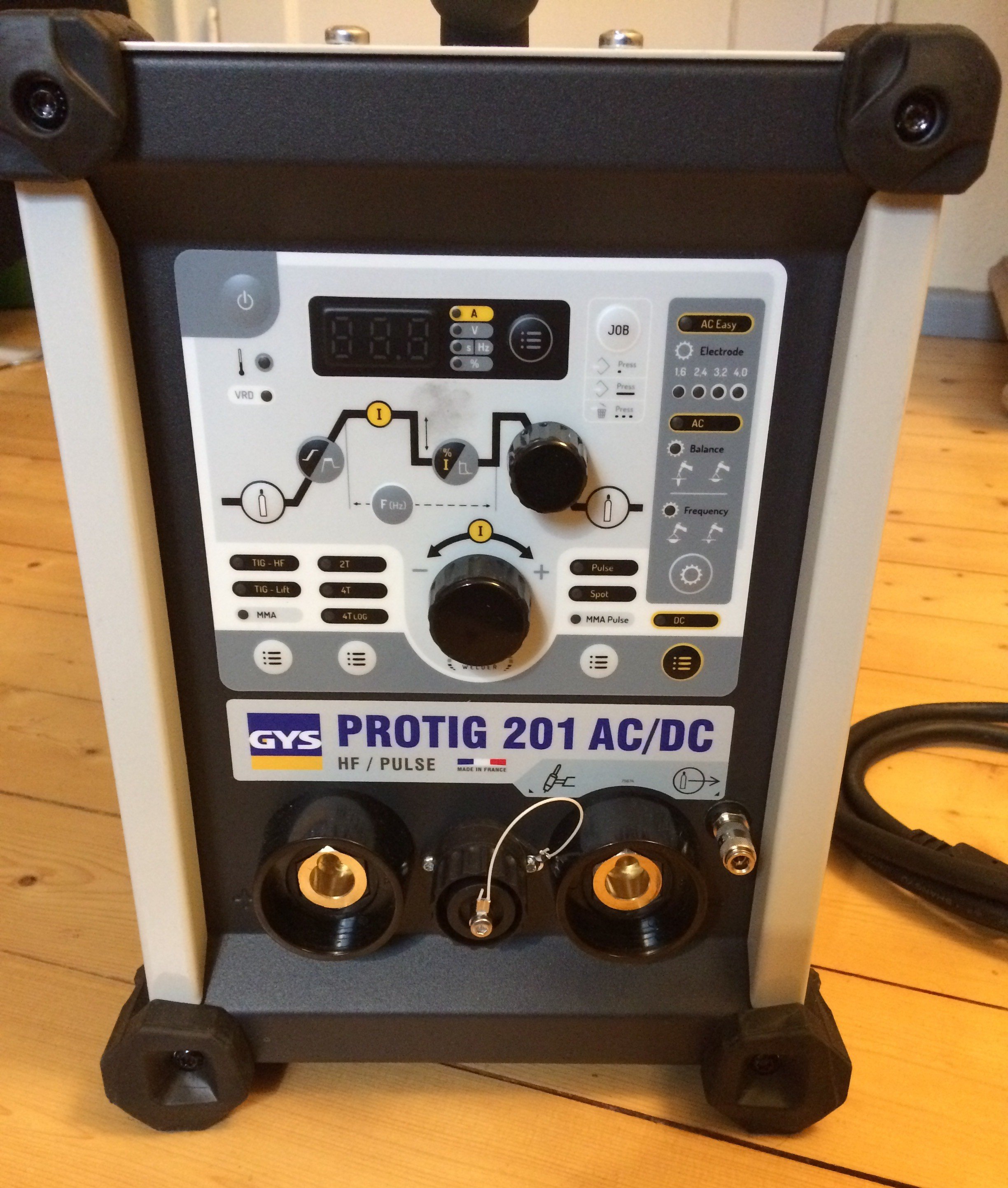
The front panel consists of a membrane keypad and two rotary encoders. Between the two Dinse-35 sockets (left “+”, right “-”) sits the connector for the torch trigger. To the right of the “-” socket is the gas connector. The keypad can be operated reasonably well with (thin) welding gloves on.
The most important specs are printed on the top of the unit:
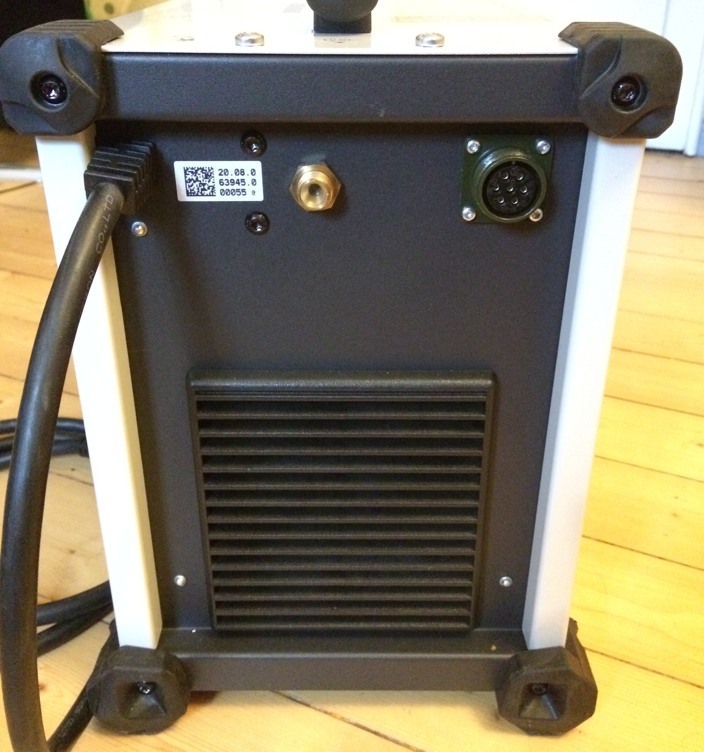
On the back, from left to right, you find the mains connector, the gas connector (G1/4" RH) and a MIL connector ( :-D ) for the foot pedal or remote control. Frankly, when I saw that this welder was just within my budget and had those connectors fitted, I was sold.
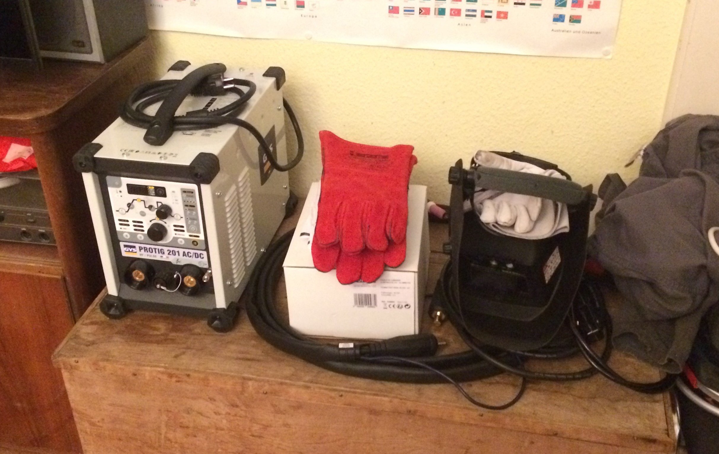
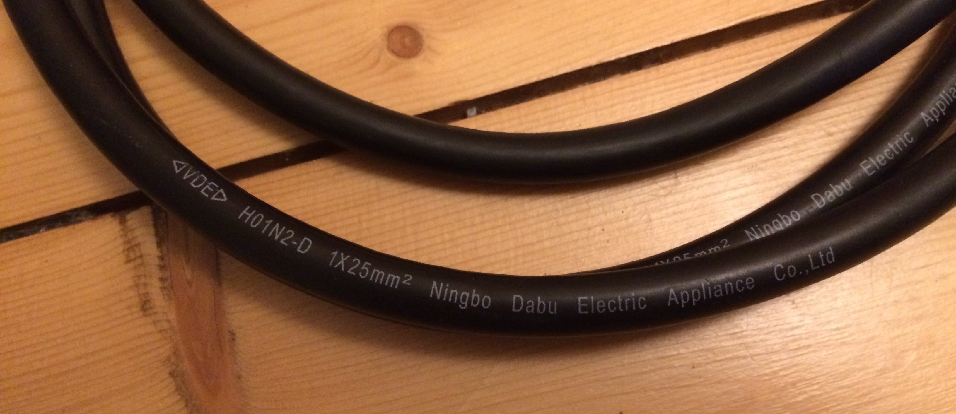
The earth lead and the electrode holder were included:
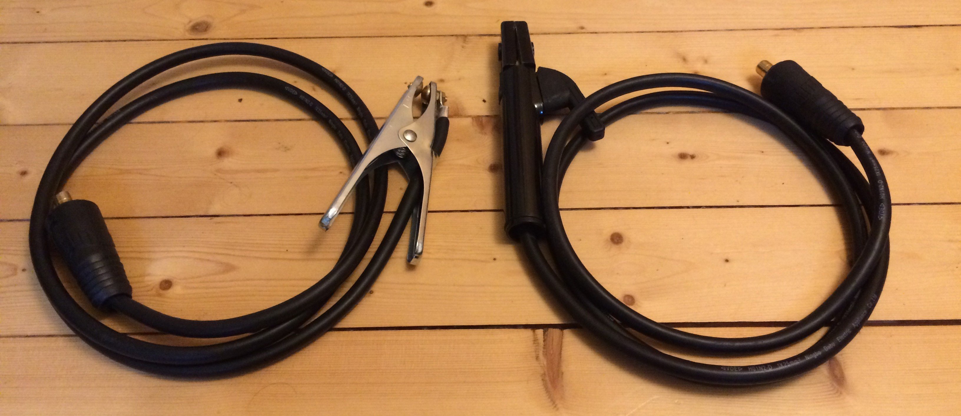
I had never heard of “Ningbo Dabu Electric Applicance Co.,Ltd”, but they can clearly make decent welding cables:
A TIG torch (ABITIG 26 from Binzel) was also included:
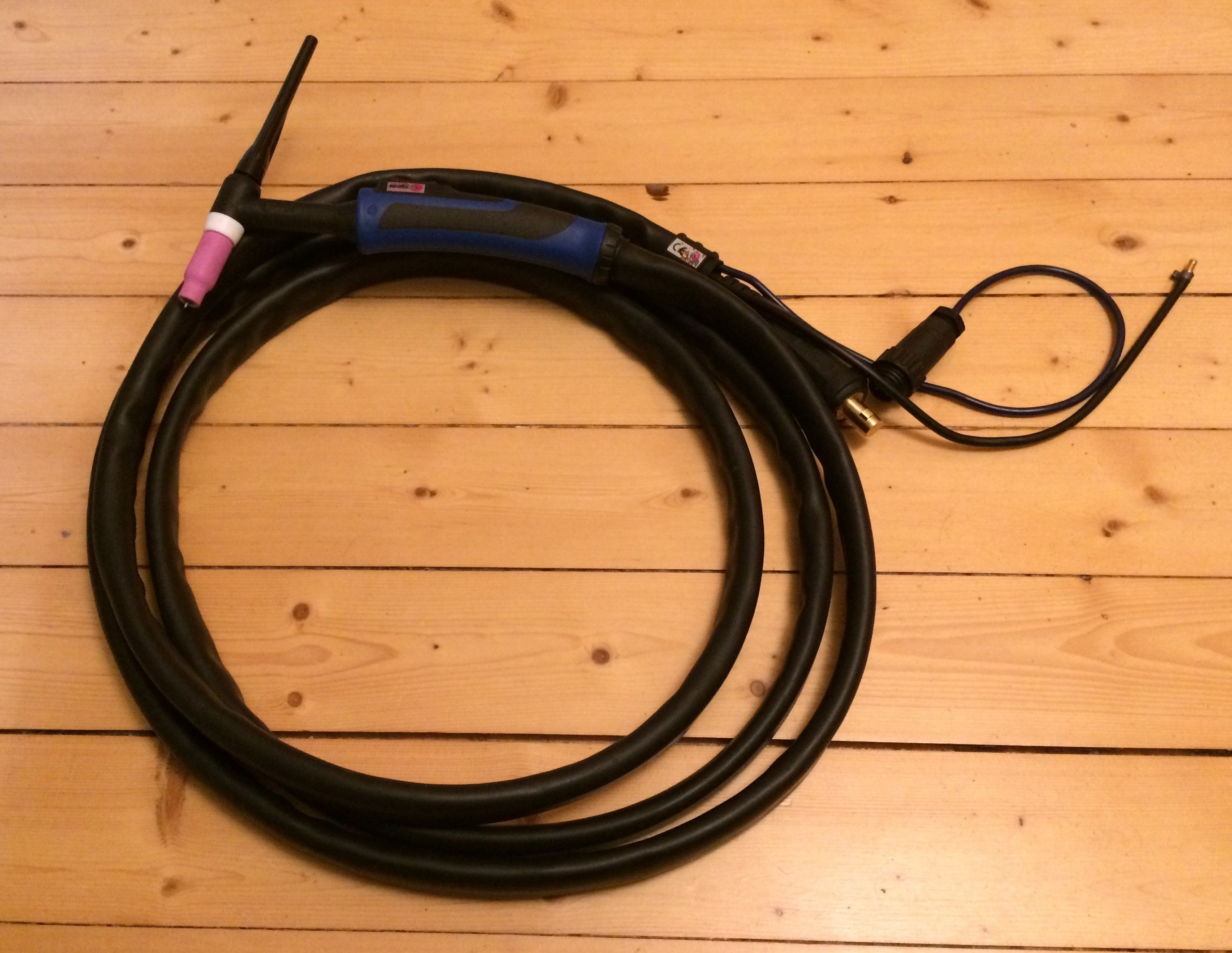
Again, decent connectors and a quick-disconnect coupling. The gas quick-disconnect has an outer diameter of 5 mm, and on the unit-side coupling you can see that it’s the series 20 fittings from legris (p. 20 onward). And please don’t ask me why these quick-disconnects are called “Rectus” in the legris catalogue…
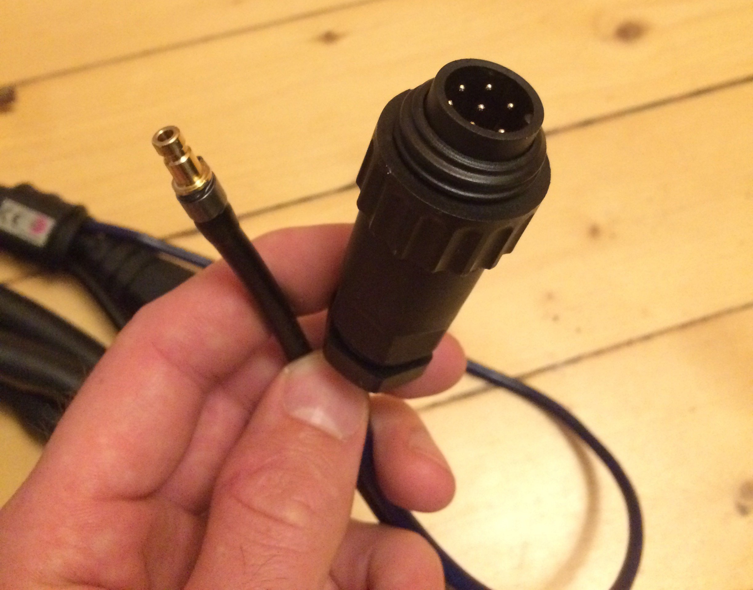
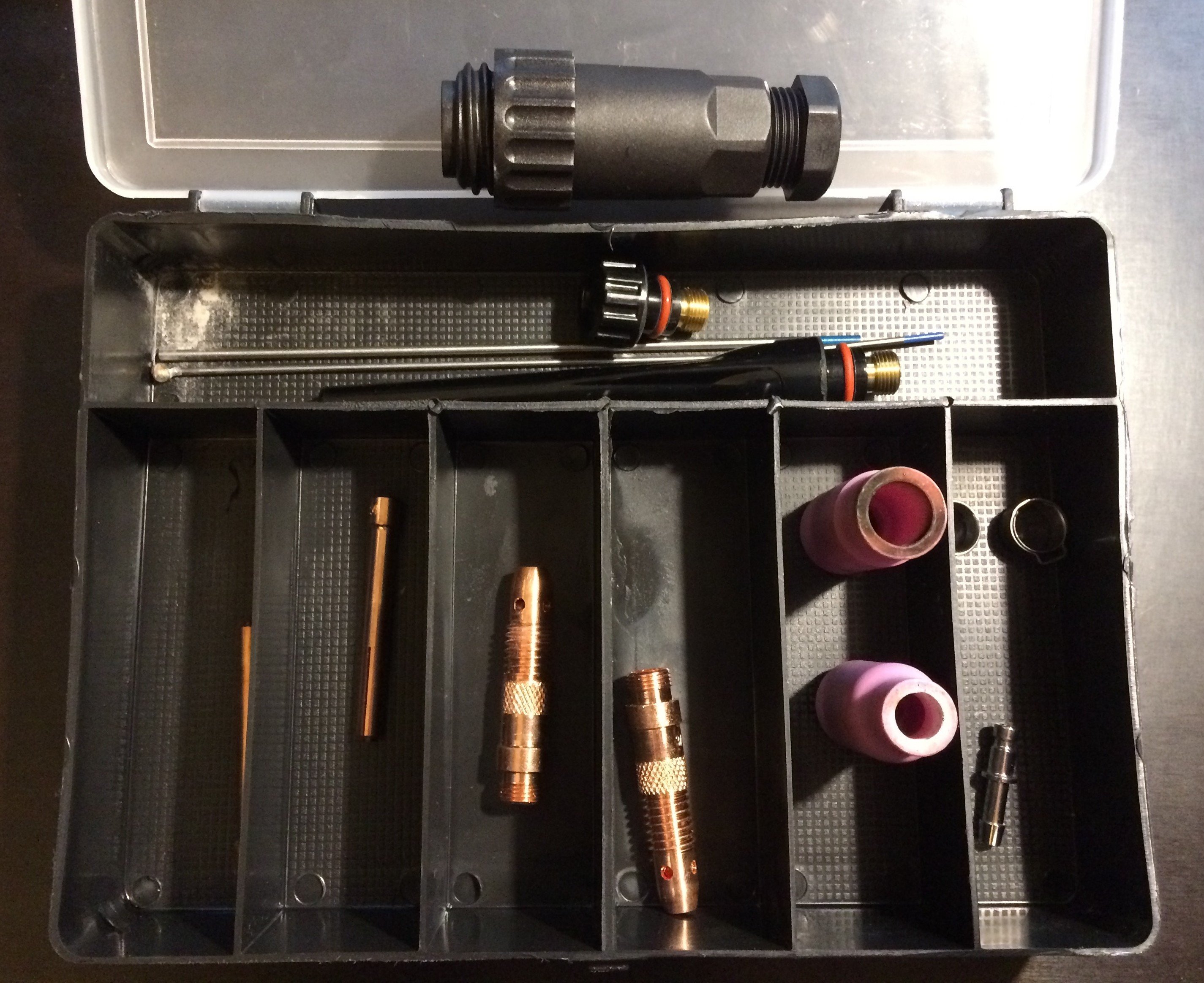
Also in the box: a small set of torch consumables, a bare connector for the torch trigger, an extra hose tail for the torch’s gas connector, a G1/4" hose nipple with 2 m of matching gas hose, and four crimp hose clamps.
Pressure regulator #
I had also ordered a pressure regulator with a protective cage. Here it turned out, unfortunately, that the hose tail was sized for a 6 mm hose; the supplied hose, however, had a 4 mm inside diameter. With a hot-air gun I was able to coax the hose to fit, so I could still get going the same evening.
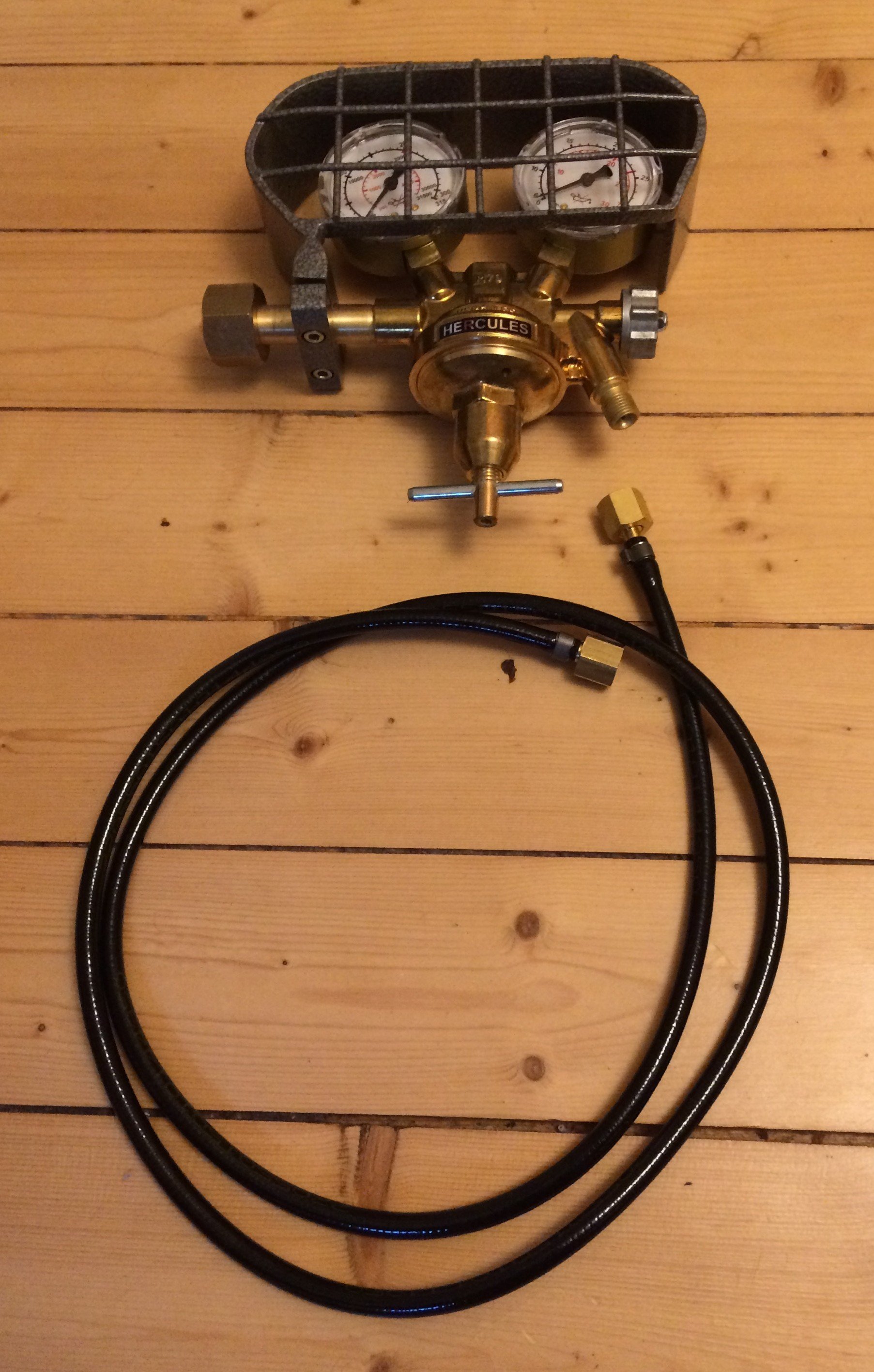
The gauge at the regulator’s outlet has a scale in L/min. It starts at 6 L/min, which (as far as I have gathered) corresponds to the typical flow for normal work… Oh well, it’ll all come out in the wash.
It was now a mystery to me how a pressure gauge (which only measures pressure, after all) can carry a flow scale. For laminar flow, pressure and flow are proportional, but for what flow resistance is this scale calibrated? If I now connect 10 m of hose, the flow resistance – and hence the flow rate at a given pressure – is quite different from working with just 2 m of hose…
In an Air Liquide regulator brochure I eventually found (buried in the flowing text) the explanation: “In a regulator with a flow-indicating gauge, the flow rate (L/min) is set with the adjusting screw and an orifice plate built into the outlet stub.”
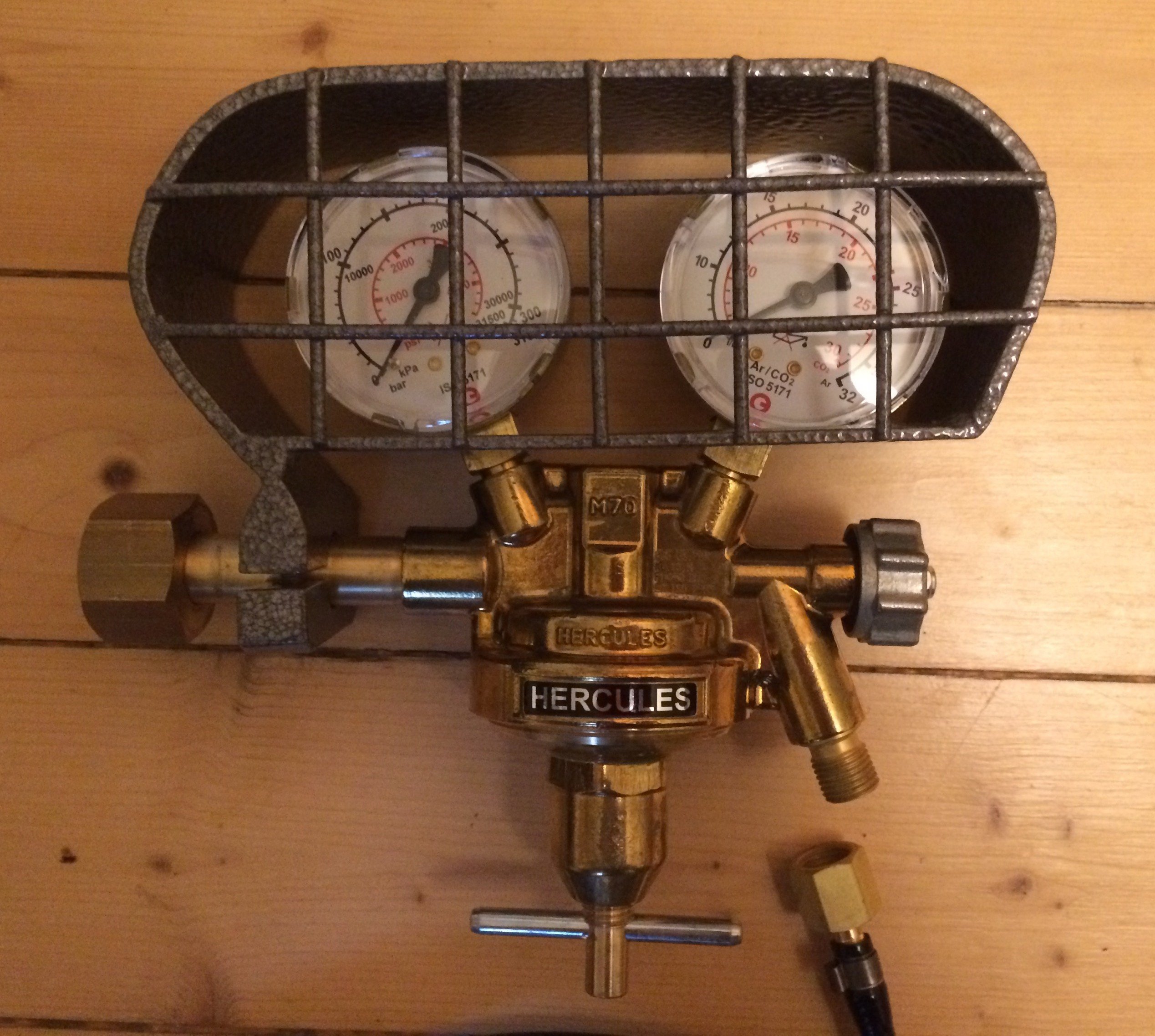
A look at the regulator:
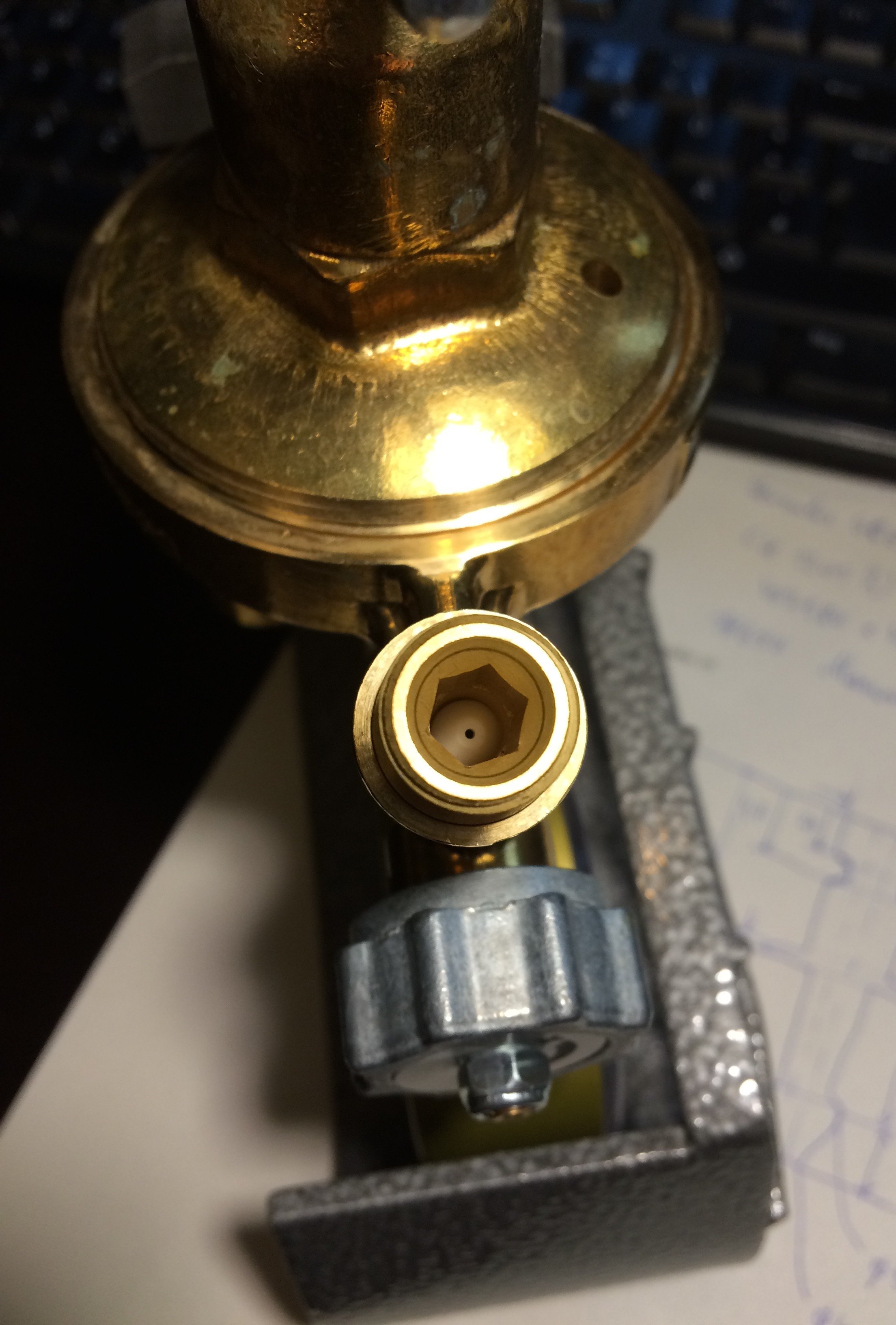
The white (plastic?) part with the small hole is presumably the orifice plate. Aha – so a given pressure builds up upstream of the orifice (which the gauge sees), and because the manufacturer designed this orifice themselves, the hole is sized so that the flow rate printed on the gauge matches. I don’t know the exact test specifications for this design, but I’d guess the calibration is done without back pressure (i.e. without hose, TIG torch, gas lens, etc., connected). Any additional flow resistance affects such a calibration, since the back pressure required for a given flow rate goes up. So if I make the hose to the torch long and thin enough, perhaps for an actual gas flow of 6 L/min I’ll need (depending on flow resistance) a reading of, say, 10 L/min on the gauge? For reproducible results you therefore want a flowmeter that plugs onto the TIG torch and indicates the actual flow at a fixed set pressure. Alternatively (which I’ll probably end up doing) you get yourself a mass flow controller (MFC, see e.g. https://www.mksinst.com/c/mass-flow-controllers), which measures the flow and regulates the pressure on its own. Used MFCs go for around EUR100 on eBay. More on that later…
Foot pedal #
For simplicity I had ordered the matching foot pedal “Fussfernregler” RC-FA1, 045682 straight away. I wouldn’t do that again; for what’s actually delivered, that’s clearly too expensive.
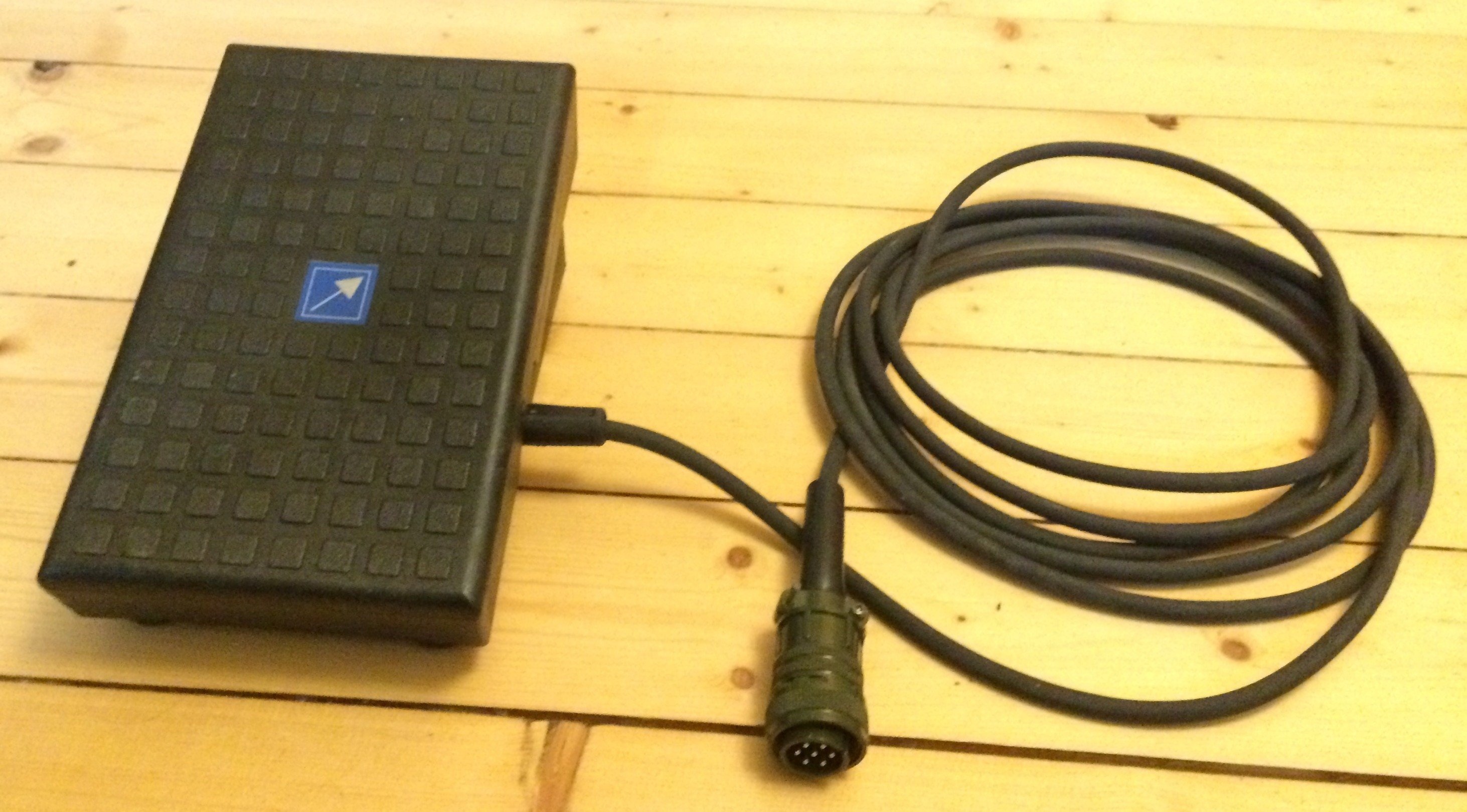
GYS apparently buys it in from “toparc”:
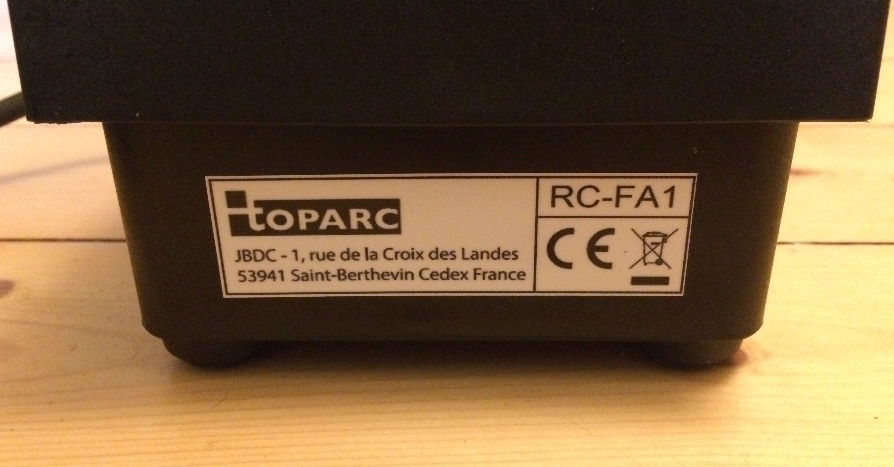
Yeah, a solid connector :-D
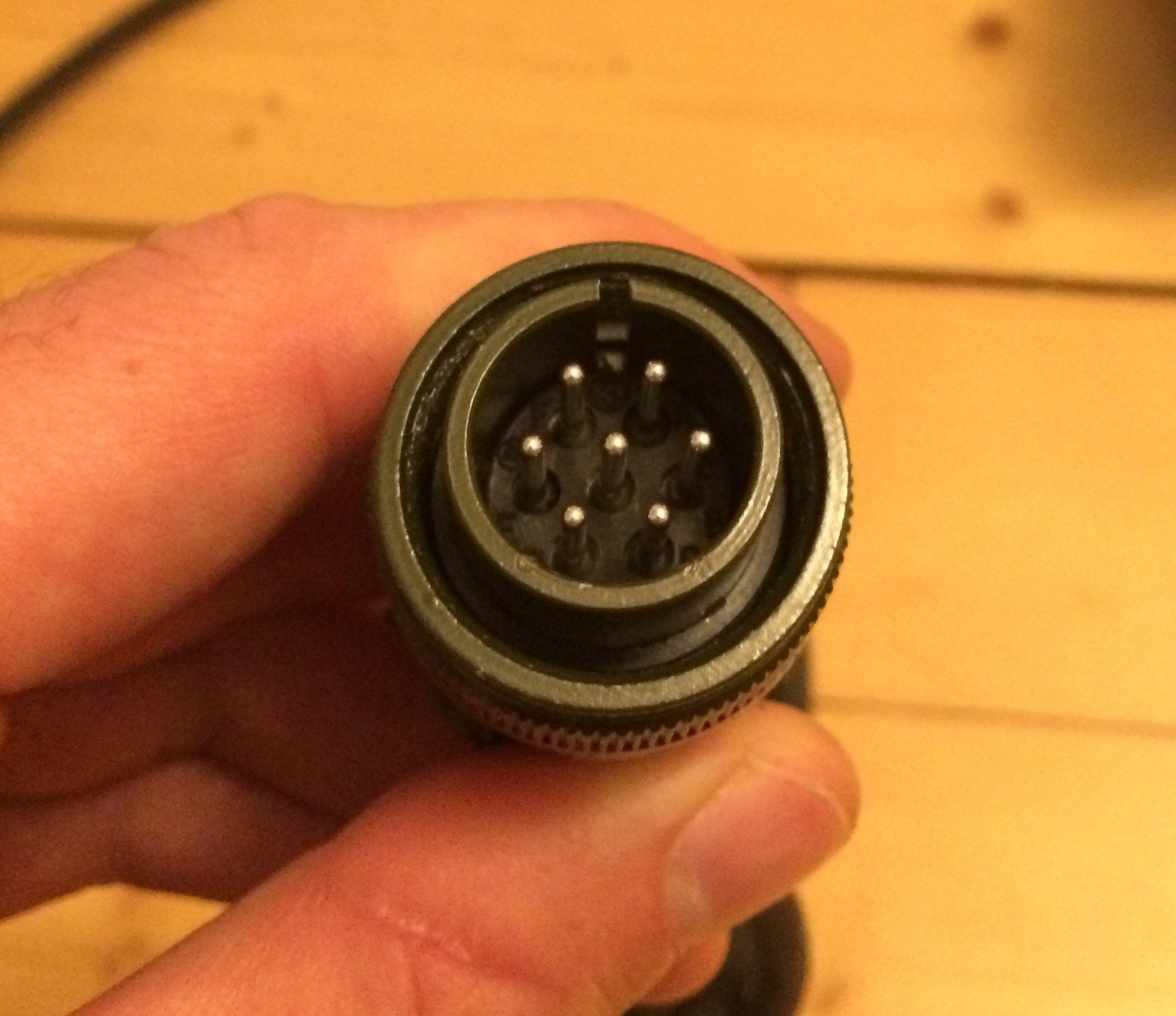
GYS also sell the MIL connector individually, although the photo in the shop doesn’t actually match the part you get. That’s probably why the photo is captioned “not contractual” in small print.
The actual designation appears to be “16S-1S”:
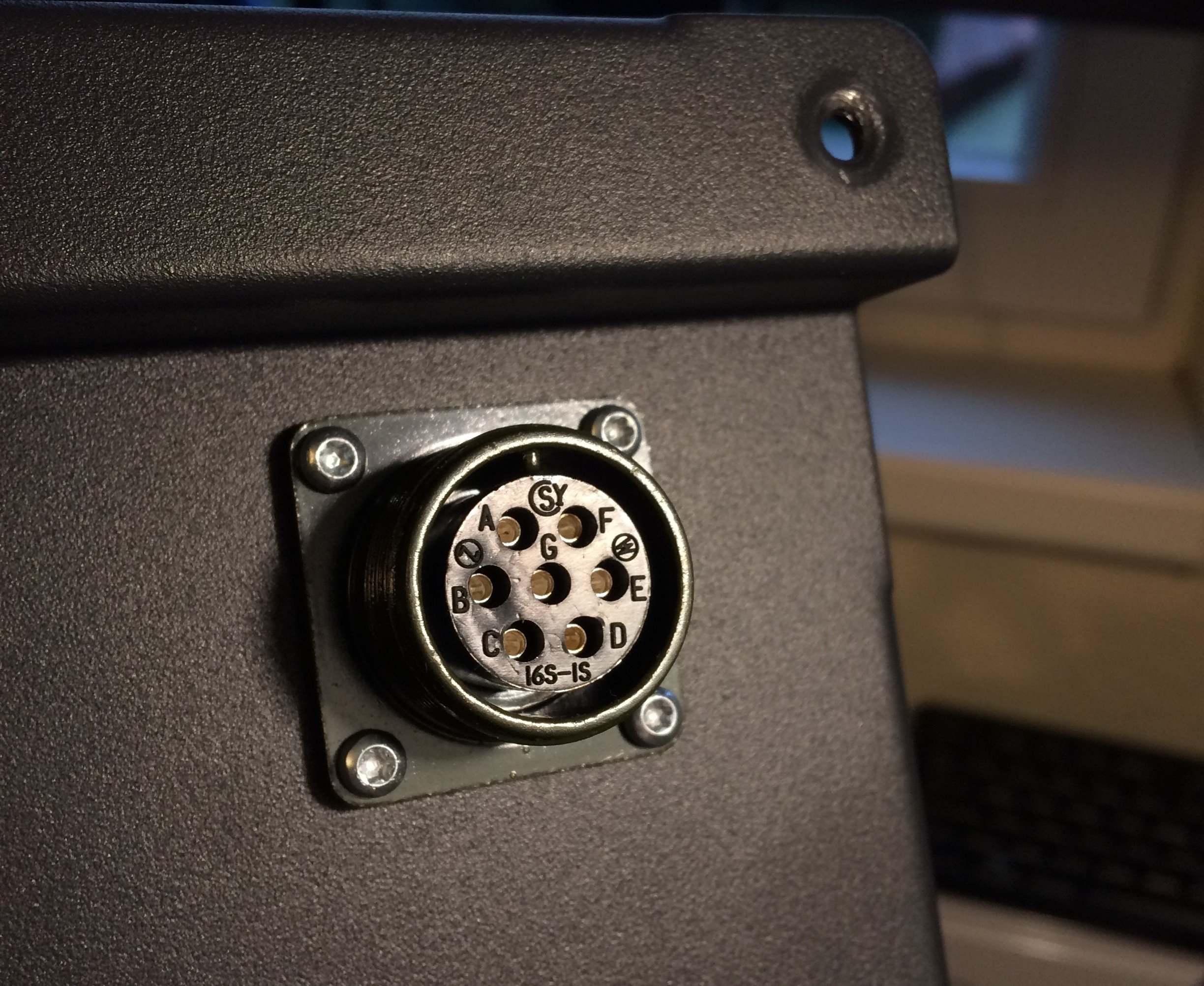
16S is the shell size and the 1 refers to the pin count and arrangement (see also RS).
A matching plug should therefore be e.g. an Amphenol MS3106A-16S-1P (298-2421 at RS) with the cable clamp MS3057-8A (298-2617 or 546-9971 at RS).
By the way, there’s also a screw-on protective cap for the remote-control socket under the designation MS25043-16D (e.g. 546-9858 at RS) for use when the socket isn’t in use.
By pressing in the studs here…
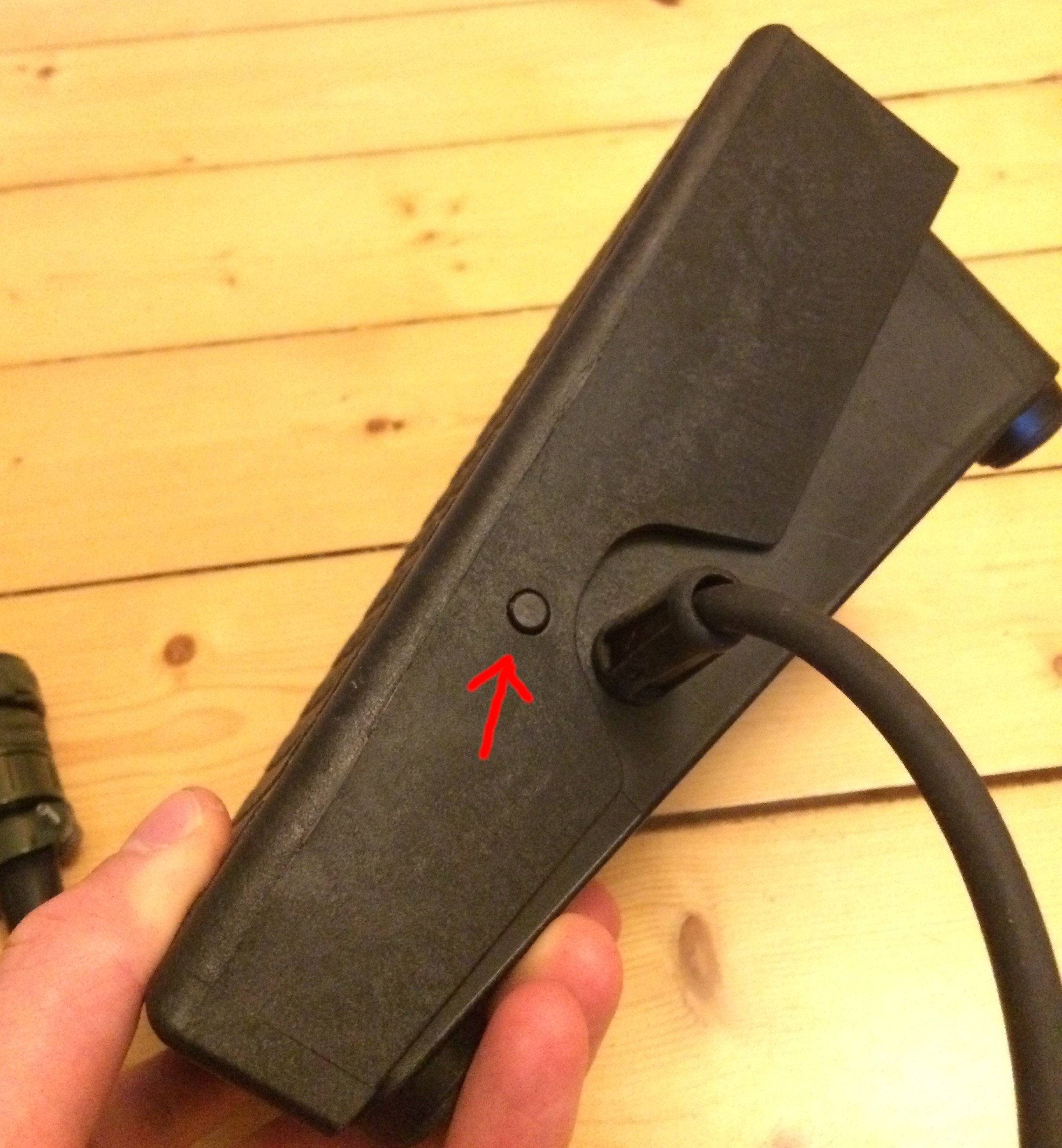
… and here, you can lift the rocker off…
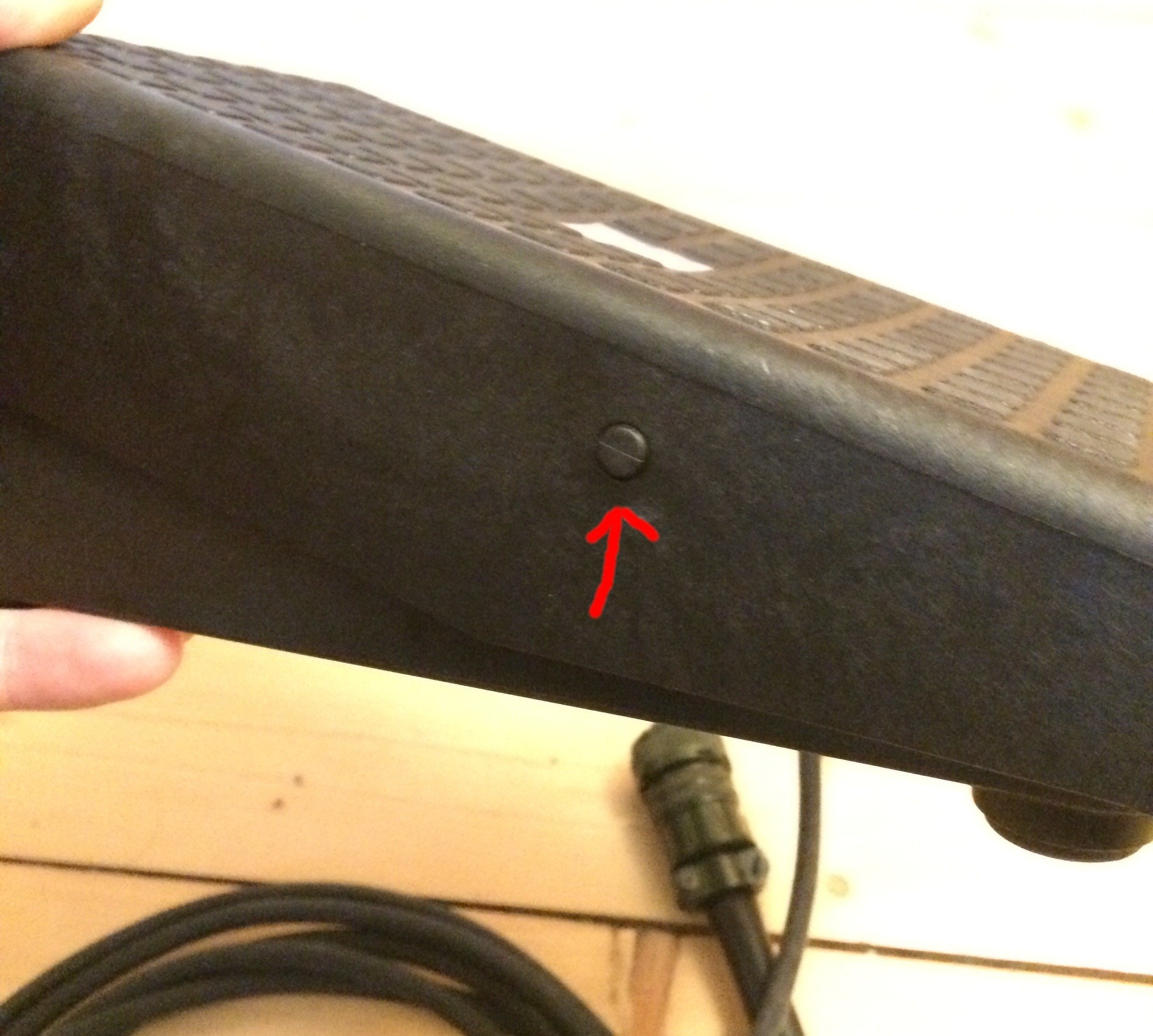
… and you get a look at the foot pedal’s innards:
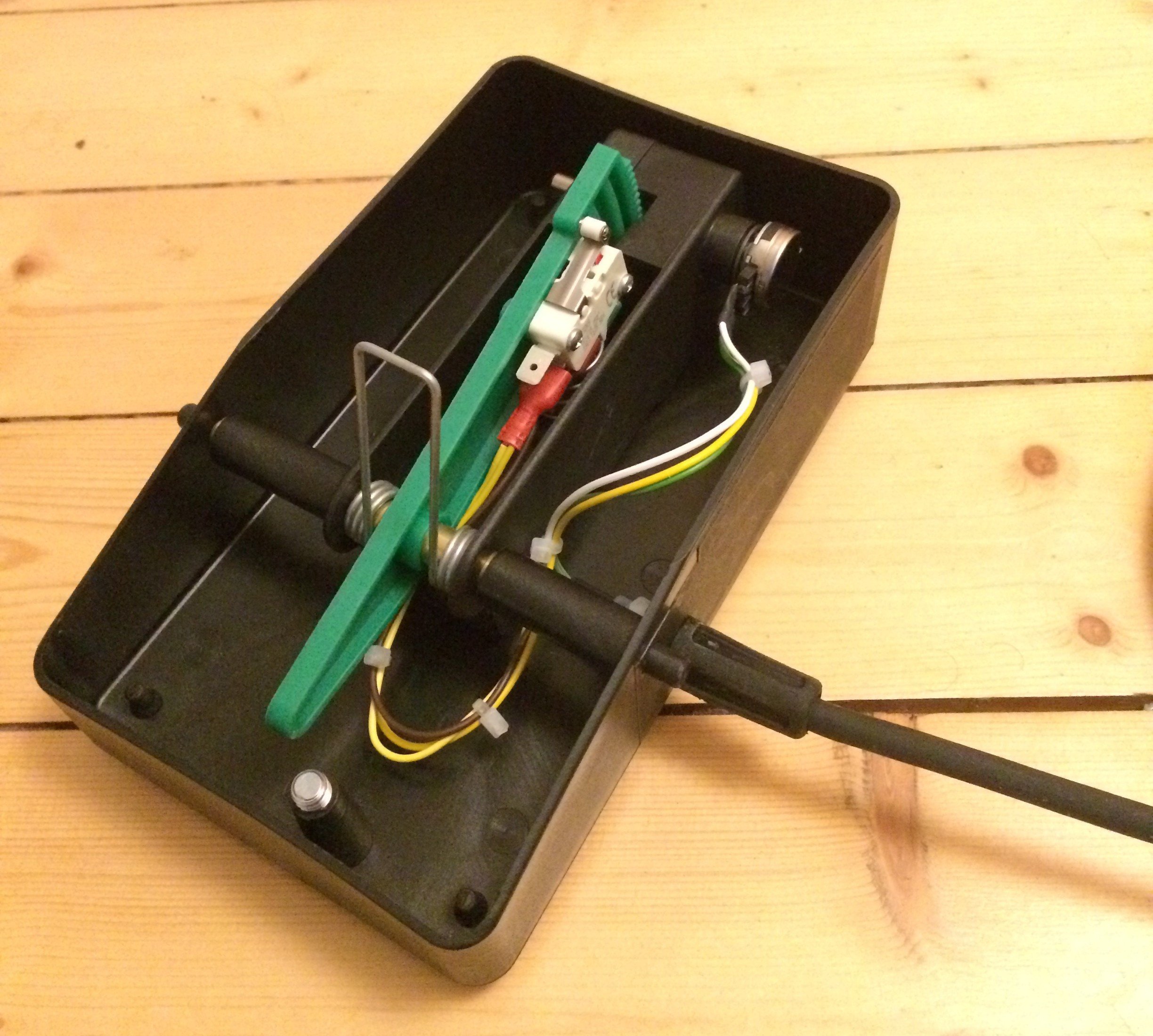
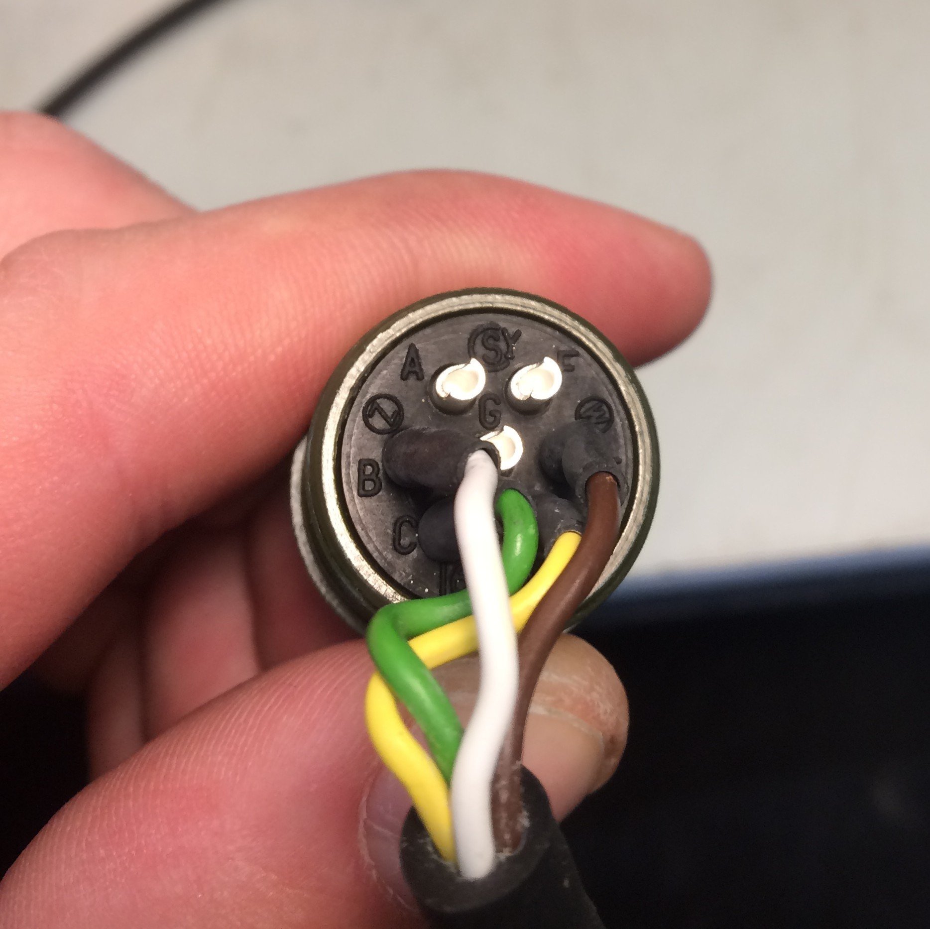
This was necessary because the foot pedal wasn’t recognised when first plugged into the welder. When a potentiometer is detected on the remote-control connector, you are asked whether you want to use the “PEd"al, a “Pot"entiometer, or “no” remote control. It eventually turned out that (presumably at the supplier?) the qualified technician soldering the wires to the connectors had slipped the pin assignment by one position. Correct is (A -> white), (B -> green), (C -> yellow), (D -> brown).
Easy to fix, but it leaves a slightly funny aftertaste. At least the pedal works perfectly now. I’ll just assume this mix-up happened at the supplier and that the welder itself is in order.
Internals #
The manual also contains the following sentence – one of the reasons I ended up choosing a GYS: “Take the cover off regularly (at least 2 to 3 times a year) and clean the inside of the unit with compressed air.” OK, so the manufacturer explicitly recommends I open the unit myself and clean the dust out?
I have a vague feeling it might be quite dirty in there; that urgently warrants a look… ;-) We’ll start with the rubber protective corners on top. The aluminium inserts pleasantly surprised me:
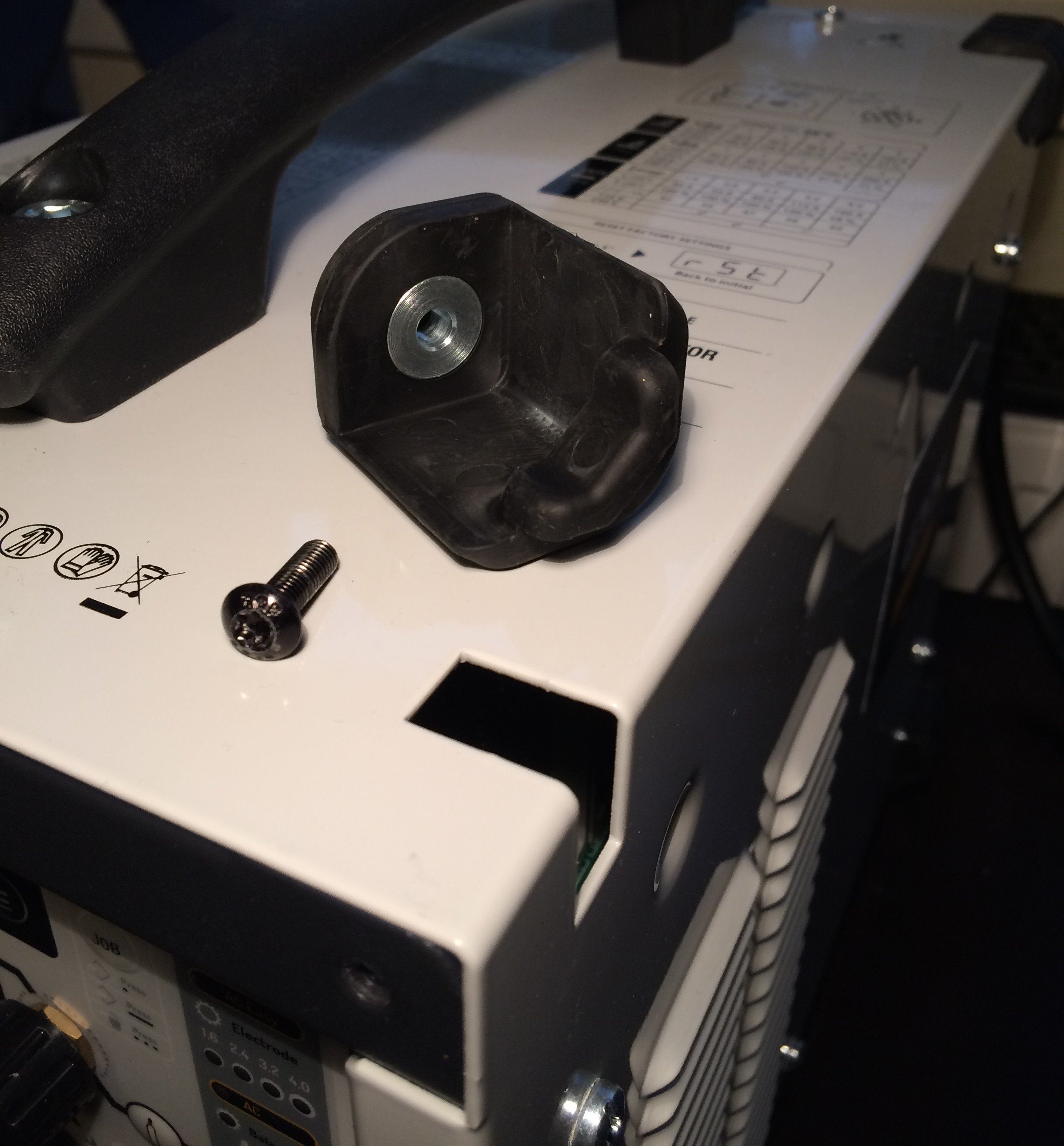
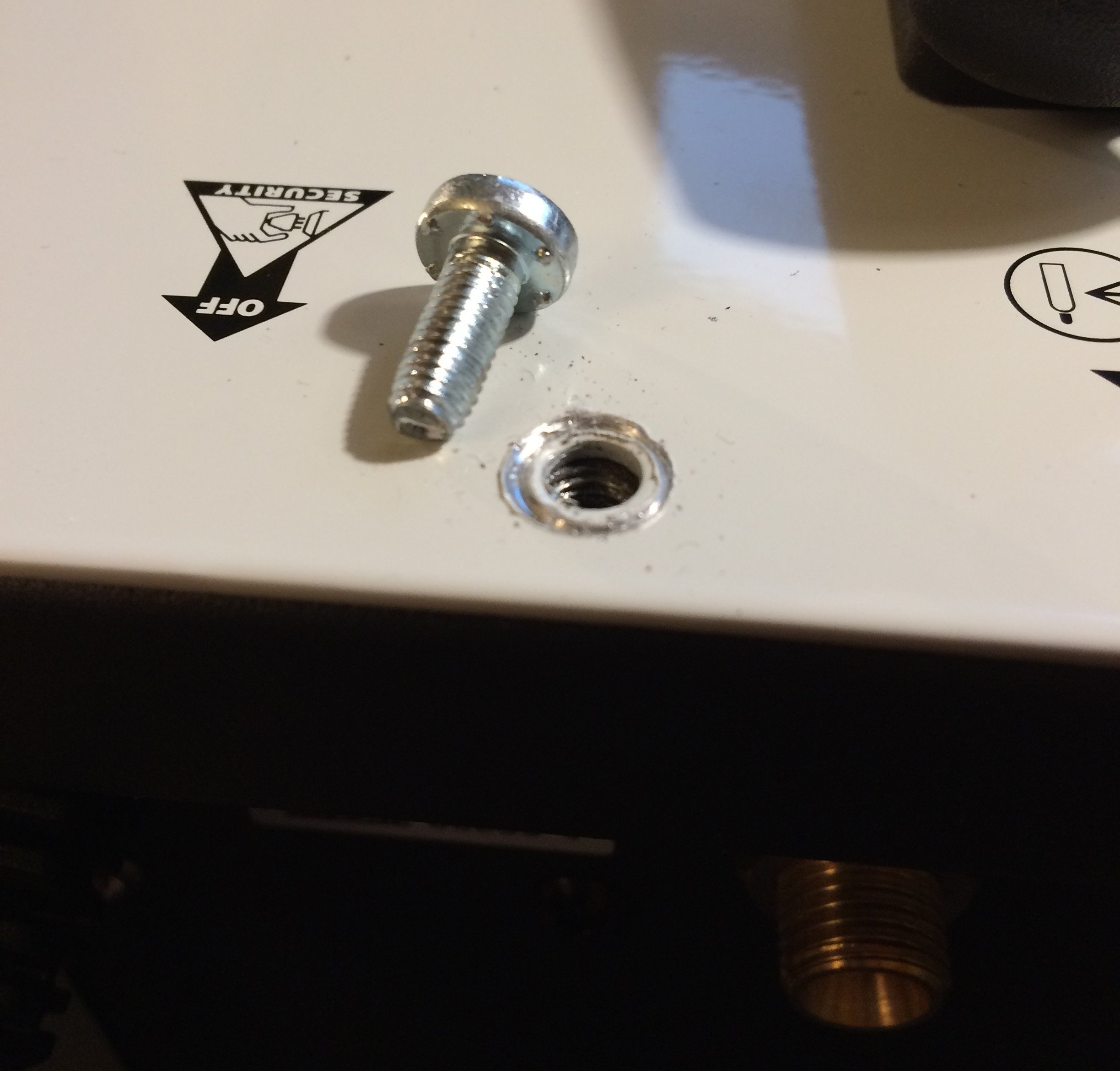
Next come the housing screws on the top and right (looking from the front). They have small studs that bite into the (aluminium) chassis. This is presumably for EMC reasons, and helps stop the screws from working themselves loose…?
The cover and the right-hand side panel are a single sheet-metal piece that can now be lifted off.
The left-hand side comes off similarly.
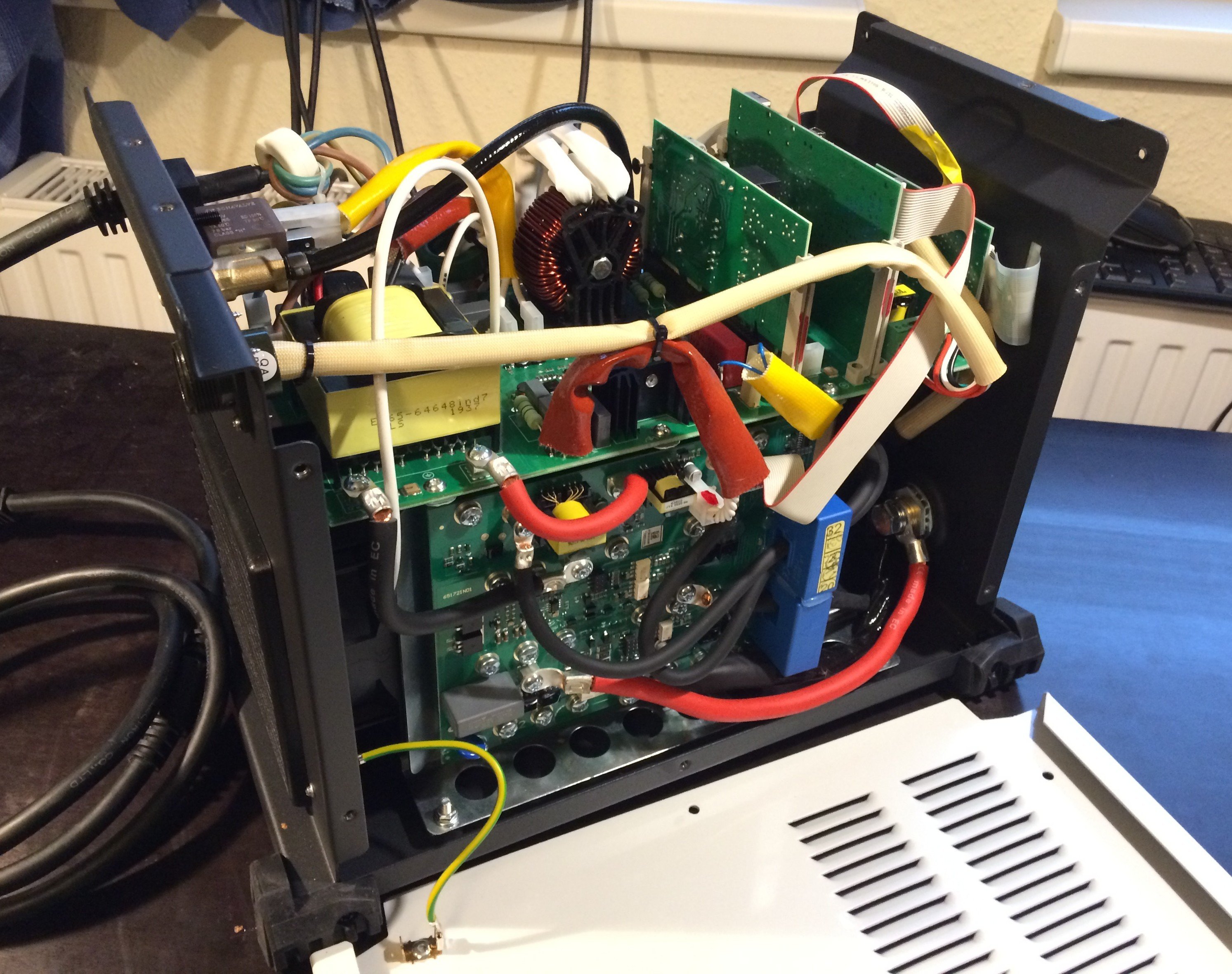
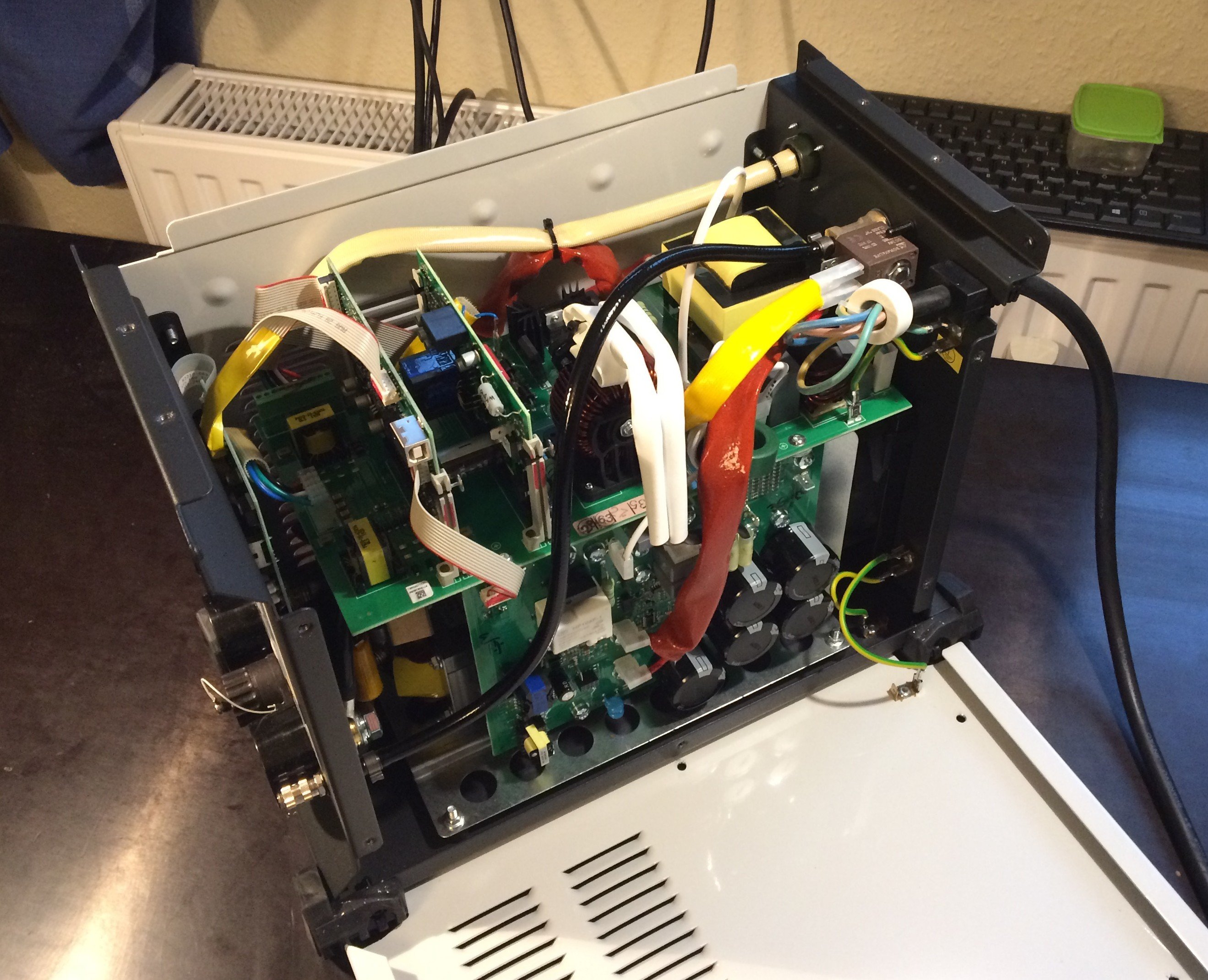
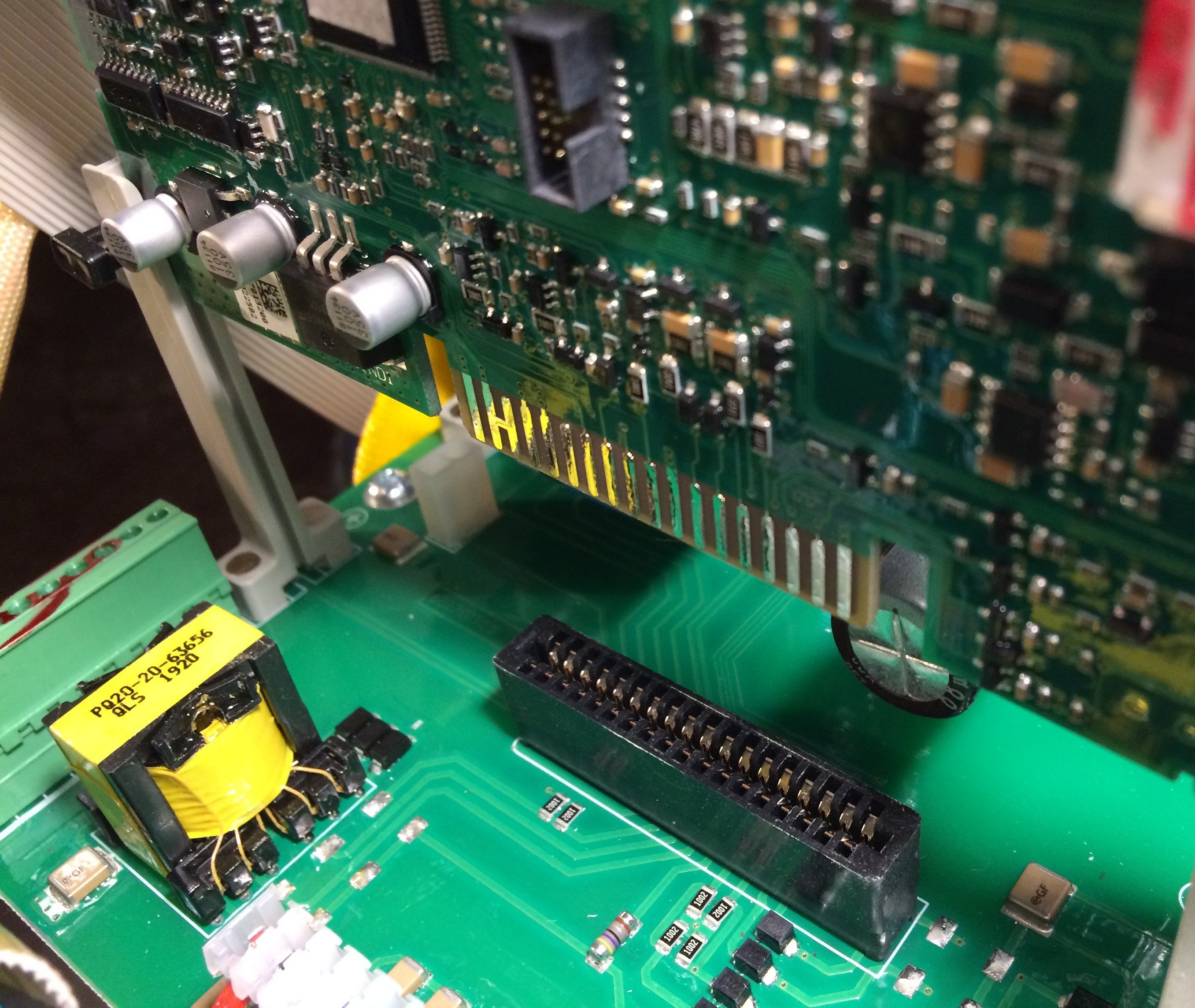
Inside, the curious observer is greeted by neatly-made boards wired together with proper silicone cables. The cable routing of the power section isn’t wildly intuitive, but that’s what the block diagram in the manual is for (right at the back, on p. 115). The only fly in the ointment for me is the use of ISA slots for the digital boards. The rest of the unit is built so well; why save those last few euros here?
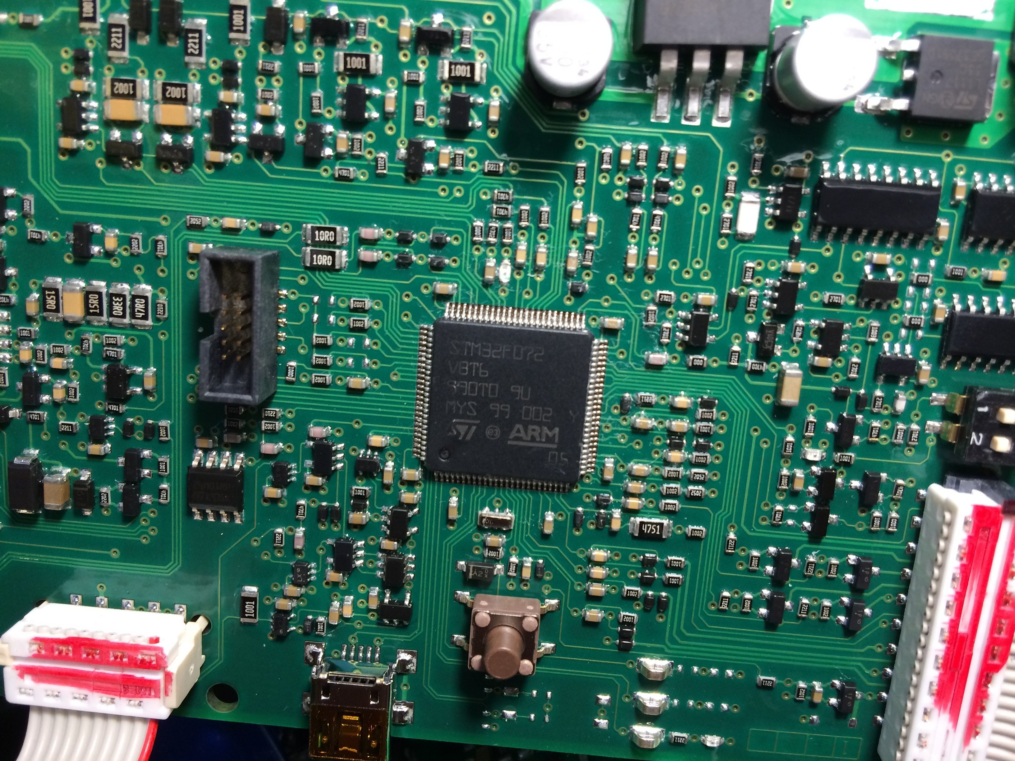
Amusingly, the processor board is driven by an STM32F072 V8T6:
There are even two (?) USB sockets.
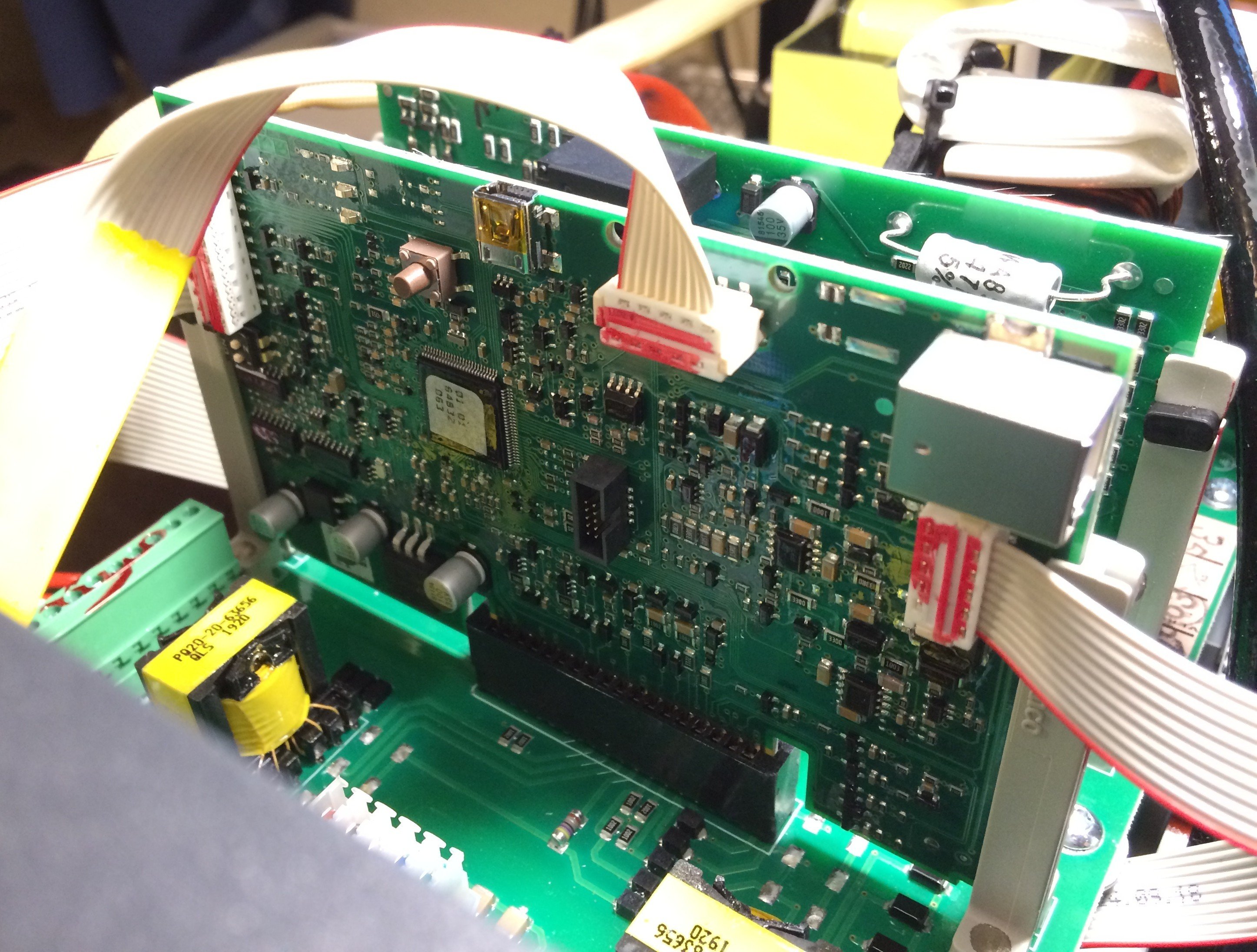
In operation a few LEDs blink, but lsusb doesn’t show any devices…
shame.
Maybe these aren’t USB ports at all, and GYS simply used the connectors
to carry debug messages over RS232 or similar.
I’ll concede it’s a bit naive to plug internal interfaces of a welding
inverter straight into a PC without first checking with an oscilloscope
what signal levels are present and whether data is being sent or received.
I did it anyway, because I could see on the board that differential
signals are routed from the sockets toward the MCU, and concluded that
these connectors at least won’t be carrying the welding current itself.
Welding tests #
The first test was stick welding. I never did a welding course or training; I just got the absolute basics explained and demonstrated to me by a good friend years ago to get started. I’ve been muddling along ever since. Consider this a warning to readers with a weak constitution: don’t faint when you see my charcoal art shortly ;-)
For electrodes I got a pack of Oerlikon FINCORD, 2.5 mm dia., 350 mm long. These were welded onto a few scrap pieces at 80 A.
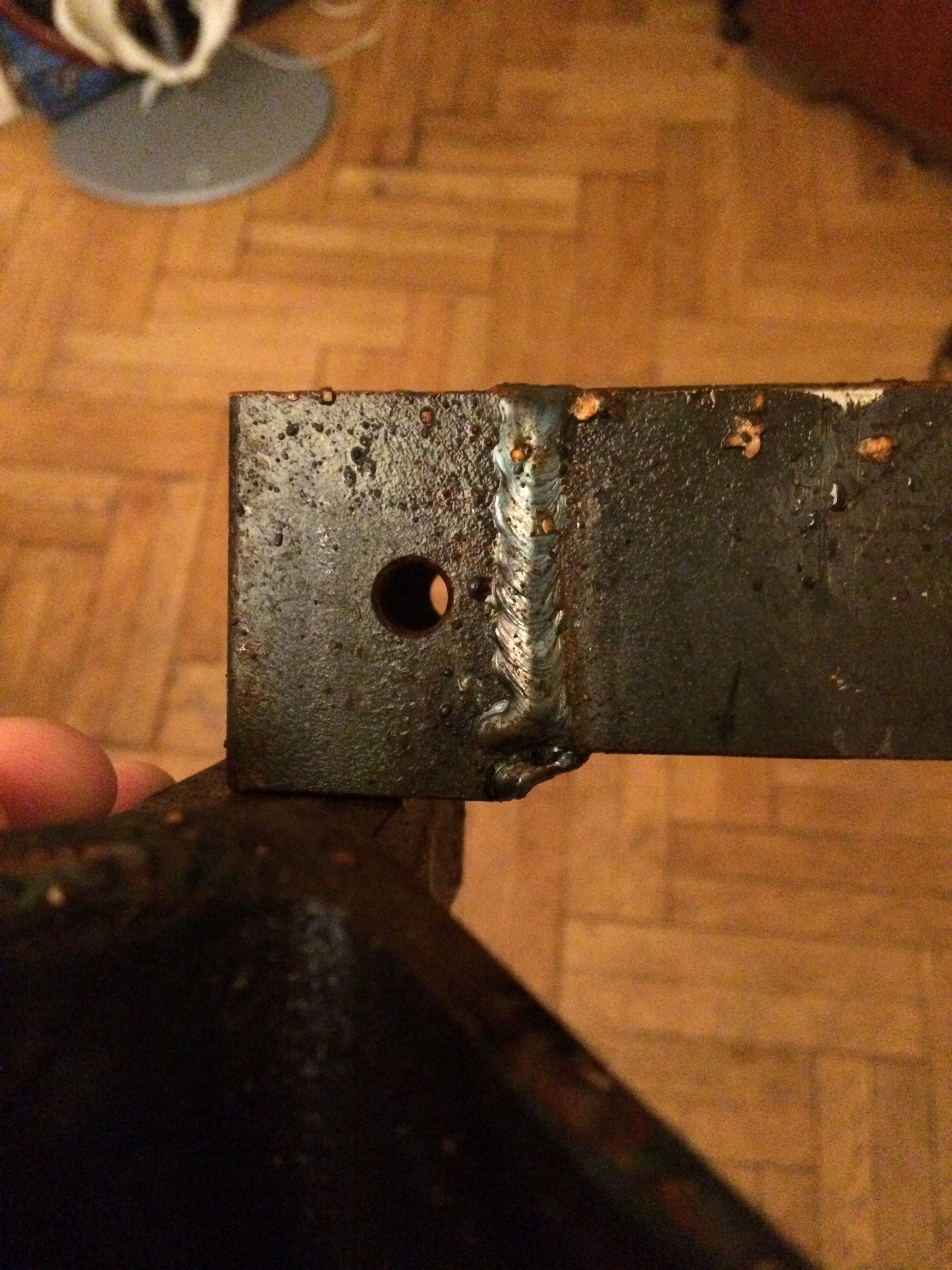
Right on:
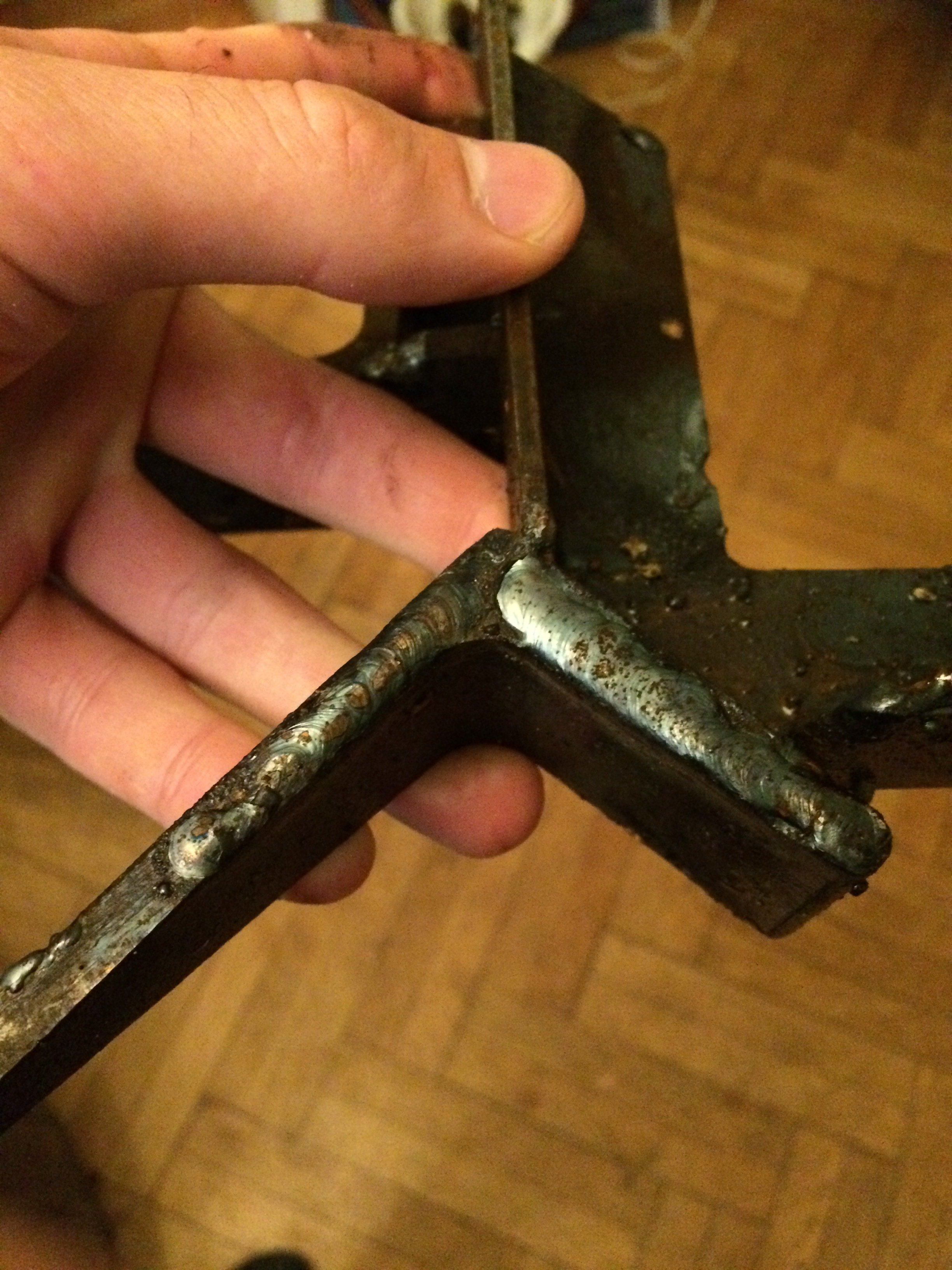
The arc strikes beautifully easily and burns wonderfully steadily. Up to now I’d only worked with transformer-based stick welders, and working with this inverter is a revelation by comparison :-)
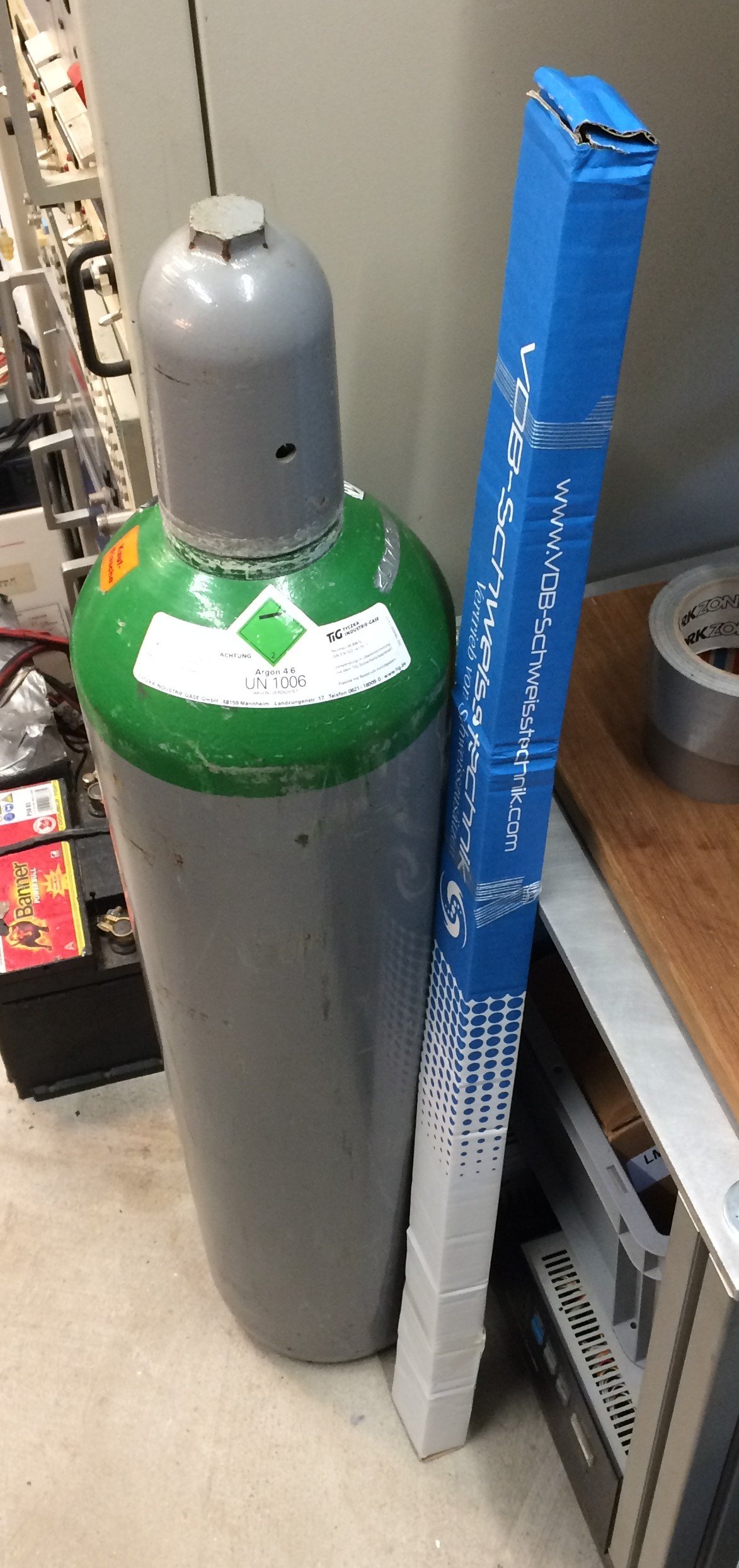
A 20 L bottle of argon 4.6 had been bought by my flatmate some time ago:
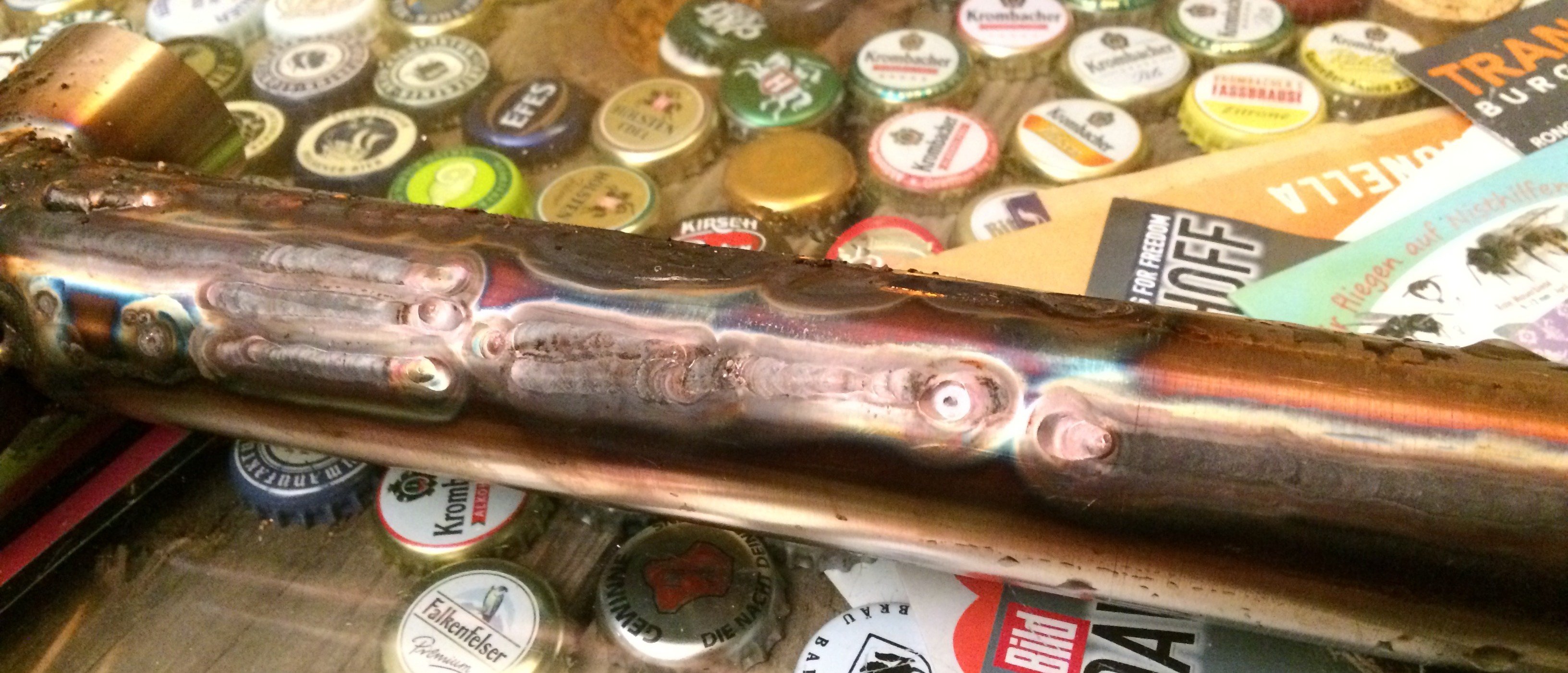
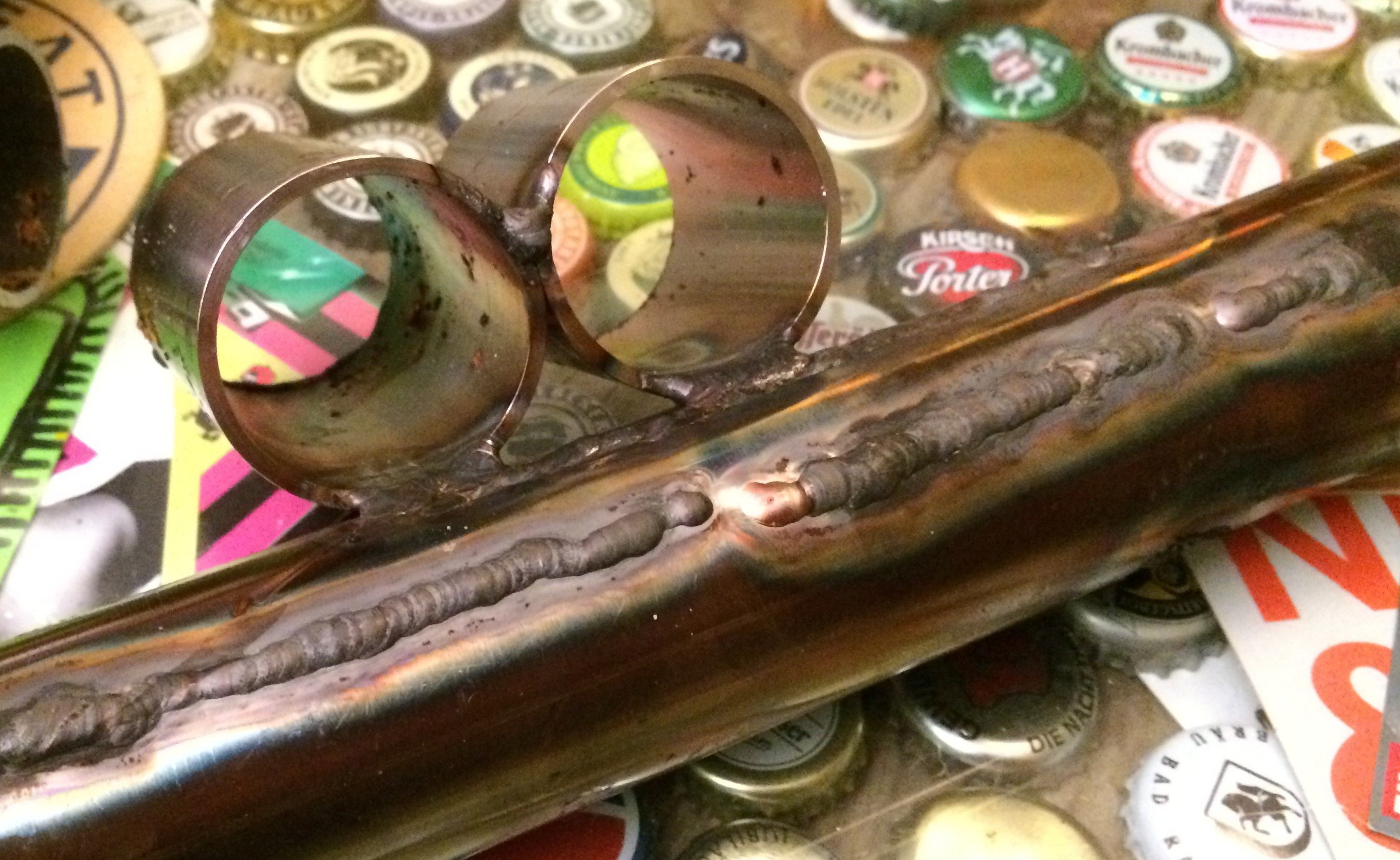
Stainless steel was up next on the agenda. First I just practised guiding the torch reasonably evenly across the work/scrap piece.
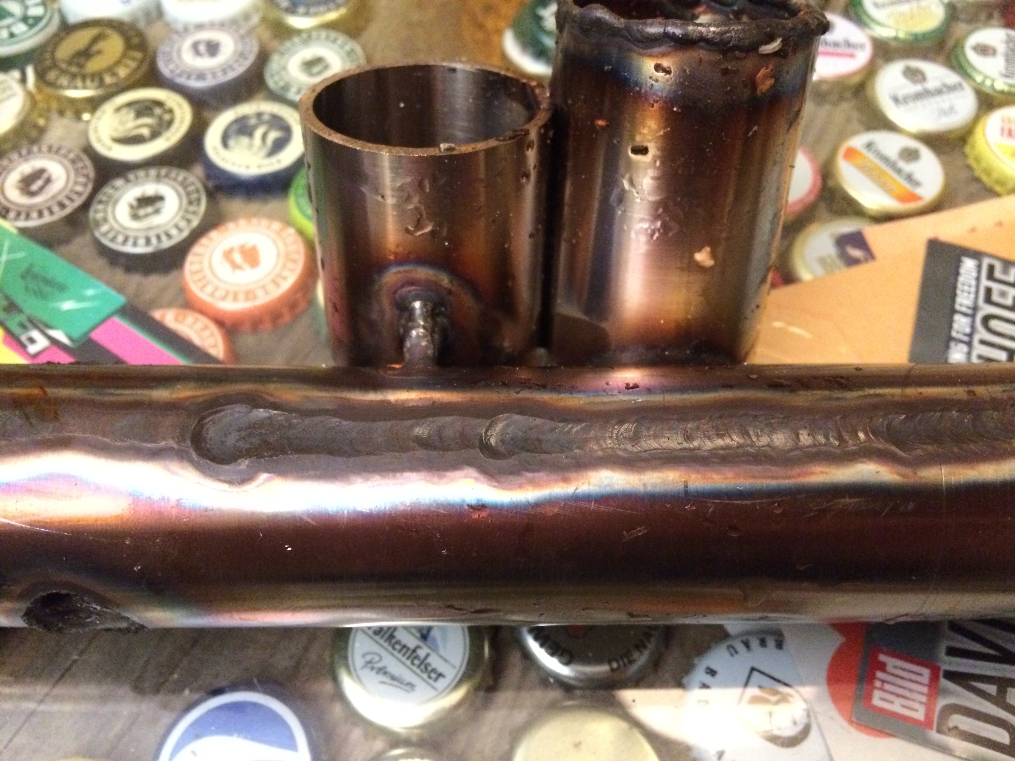
Then a bit of playing with the gas flow:
I had also pre-ordered some stainless filler material…
… as well as a bit of silicon bronze for TIG brazing:
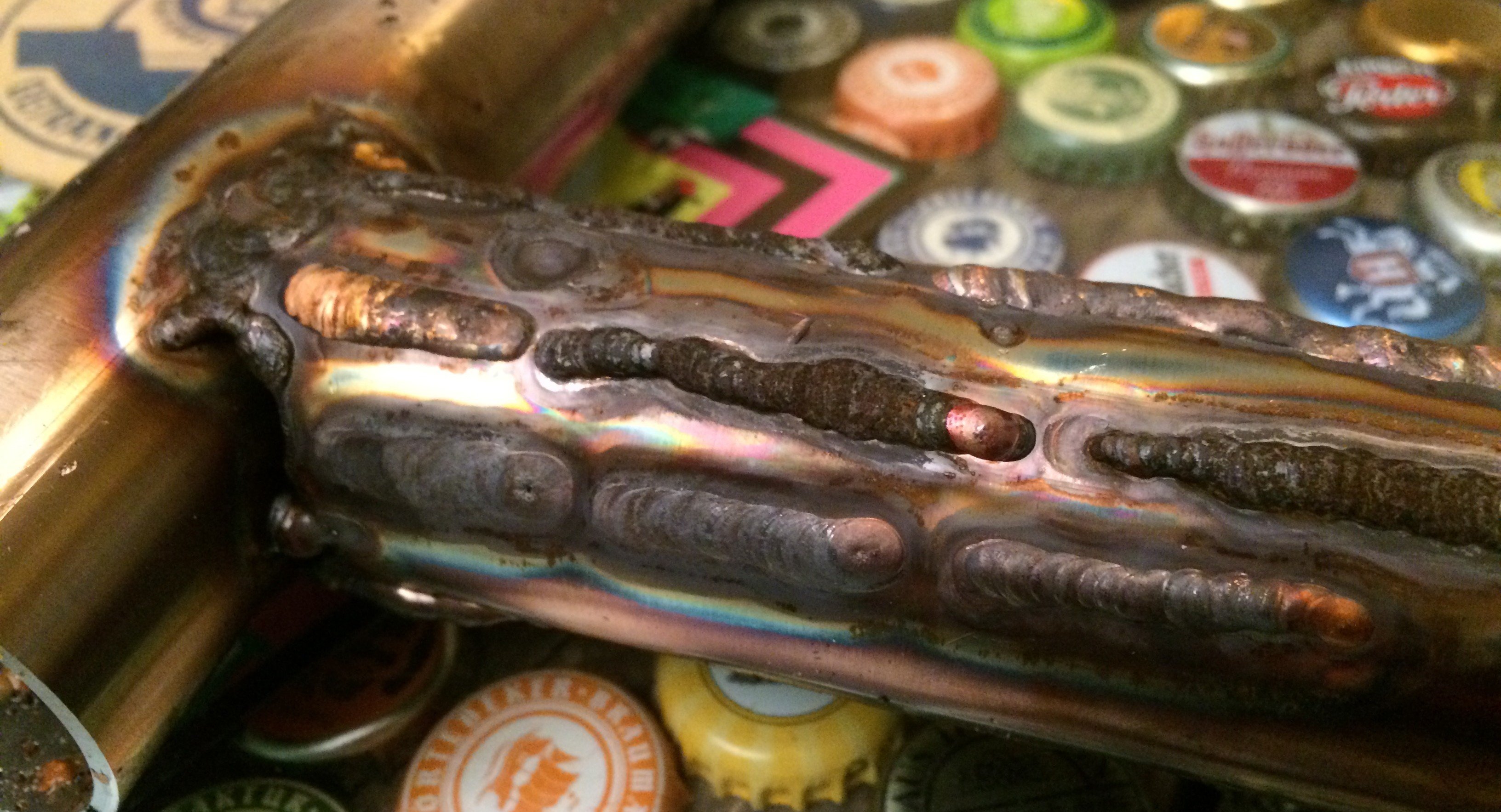
Take-away so far: nobody is born a master. A lot of practice and machine setup is going to be needed before clean beads start tumbling out. For that, I picked up a job lot of stainless sheet on eBay-Kleinanzeigen and will be spending the coming days and weeks getting some feel for TIG welding…