Saupe DLZ180x450 #
After buying a nice new lathe a while back, I am finally getting around on the train today to introduce it properly here.
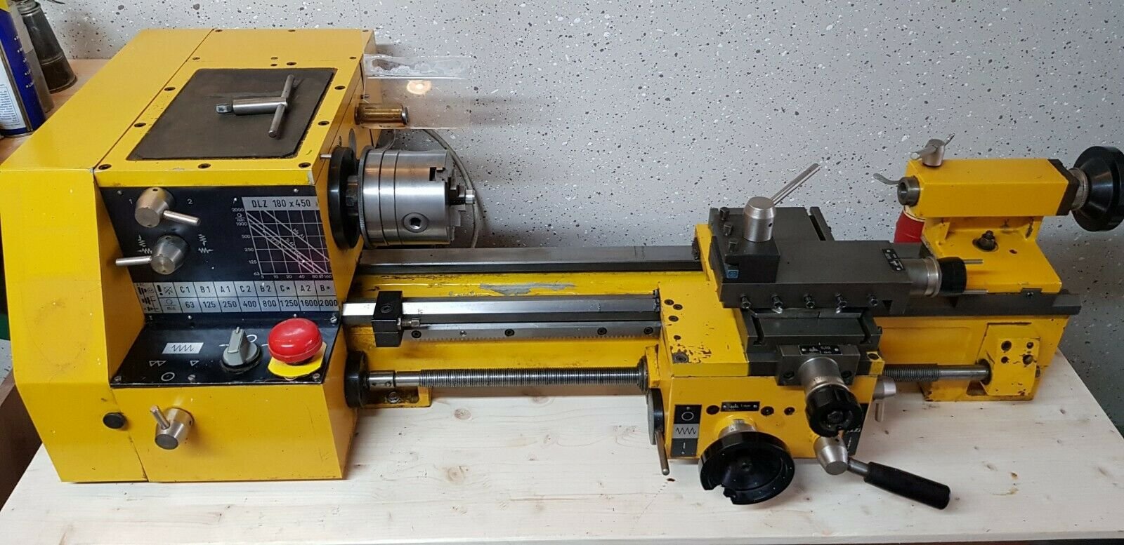
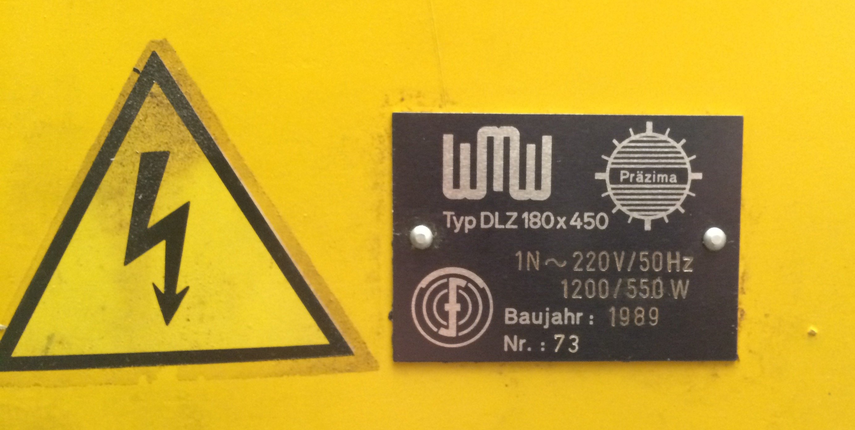
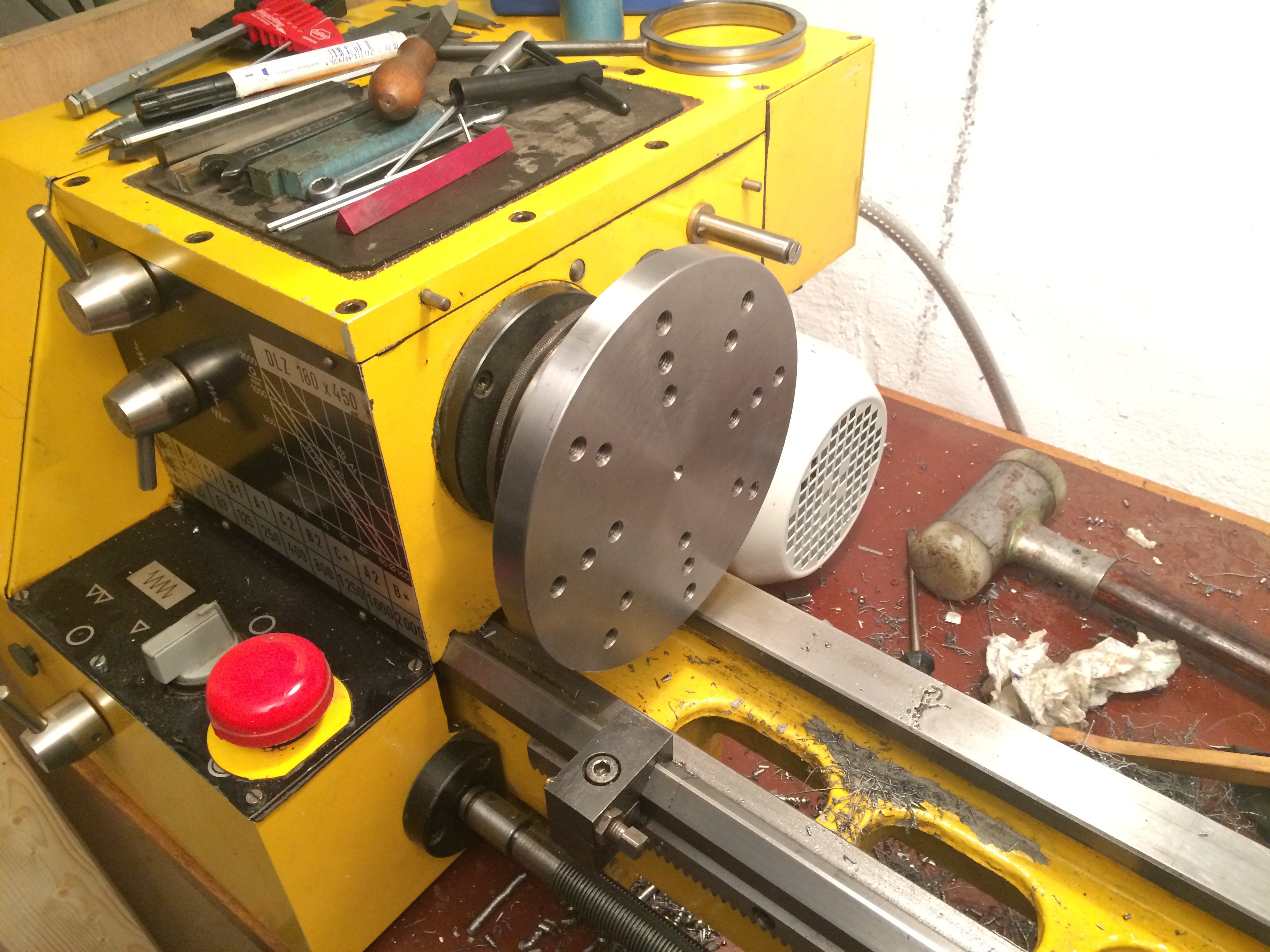
It’s a DLZ180x450 from Saupe in the former GDR, sold under various labels; amongst others, this machine was sold by the Neckermann mail-order catalogue under the brand name Bullcraft, and by the WMW conglomerate. The name “Praezimat” also pops up (to distinguish it from the “Hobbymat” SD300)…
A friend of mine who’s a turner had recommended this type of machine years ago, but unfortunately they’re very rare on the market. Recently, however, two of them came up on eBay simultaneously (the other one also made an appearance on the Zerspanungsbude forum: Post #503000), and I couldn’t resist – especially as the machine was being sold in Munich, so I could combine the pickup trip with visiting my partner ;-)
This compact and accurate machine now graces my little basement workshop, and I’m gradually bringing it back to full working order. It was originally bought by a model maker who used it mostly for plastic parts; that’s why I found massive amounts of plastic chips in the change-gear box and in all the less-accessible places of the machine. I took it over from the (presumed) second owner, who had wanted to use it to make bicycle thru-axles but in the end never got around to it.
Included were the complete change-gear set, the original tool kit, the user manual, and a few accessories (live centre, drill chucks, lathe tools). The price is on eBay anyway; I ended up paying EUR650 for the machine, which – given the work to do listed below – I consider an absolute steal.
A quick overview of the machine’s data:
| Parameter | Value |
|---|---|
| centre height over bed | 90 mm |
| centre distance | 450 mm |
| spindle nose | short taper 3 per DIN 55021 with internal MT3 |
| spindle bore | 20 mm |
| tailstock taper | MT2 |
| cross-slide travel | 90 mm |
| compound-slide travel | 95 mm |
| tailstock quill stroke | 60 mm |
| centre height over compound | 16 mm |
| leadscrew pitch | 2 mm |
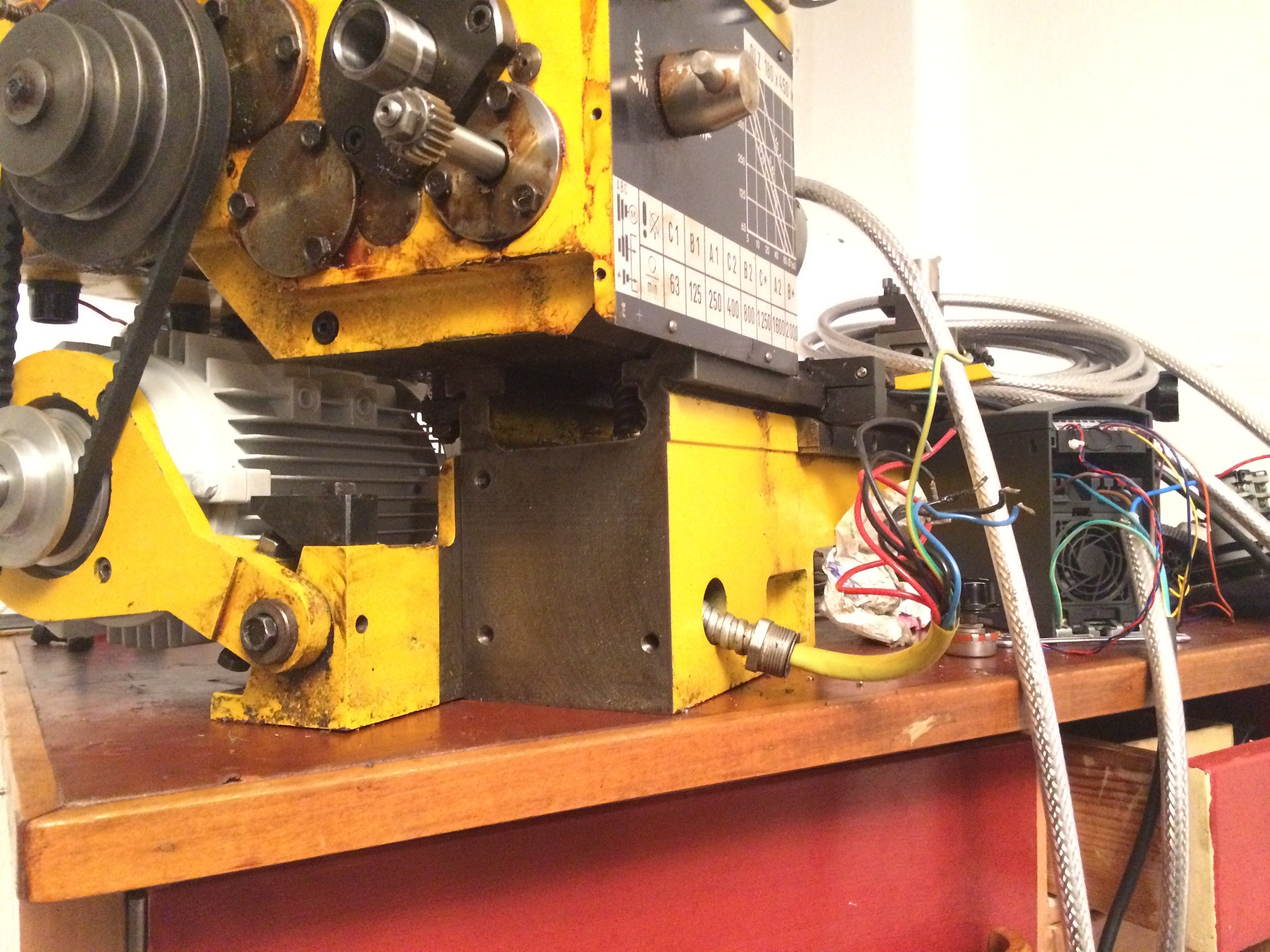
| spindle speeds with original motor | 63, 125, 250, 400, 800, 1600 rpm |
| motor power | 0.55 kW |
| total weight | 120 kg |
| footprint (LxWxH) | 1060x580x330 mm |
A number of features of this machine make it a sustained joy:
- a large, flat shelf on top of the headstock for e.g. tool holders, callipers, …
- a real short-taper spindle nose
- automatic longitudinal and cross feed
- two opposing angular-contact ball bearings on the front of the main spindle
- thrust ball bearing and needle bearing for radial support of the leadscrew end
- ball-bearing-mounted feedshaft
- overload clutch in the feedshaft drivetrain
- through T-slots in the cross slide
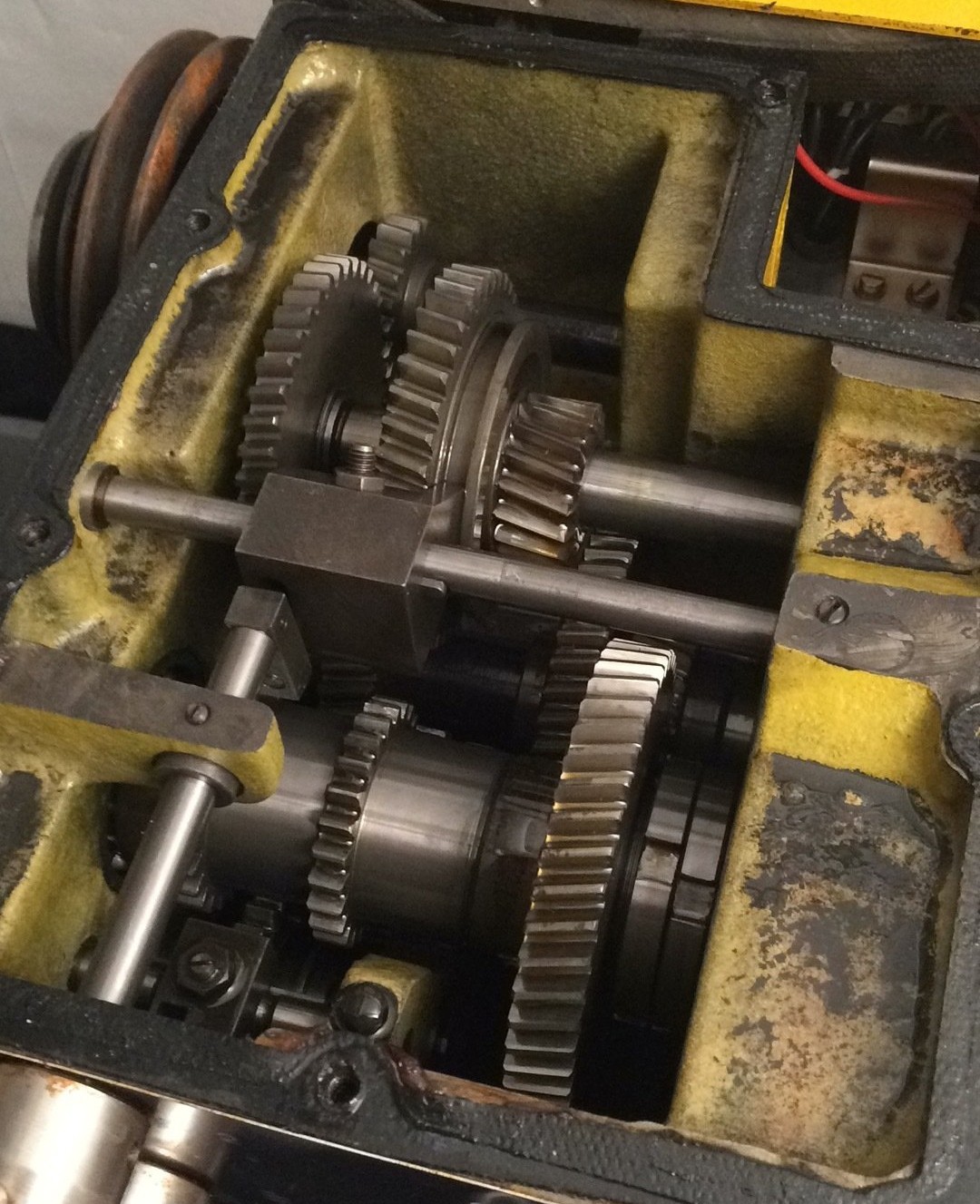
- helical, oil-bath-running headstock gearbox
- sliding-gear box instead of a tumbler reverse for changing the feed direction
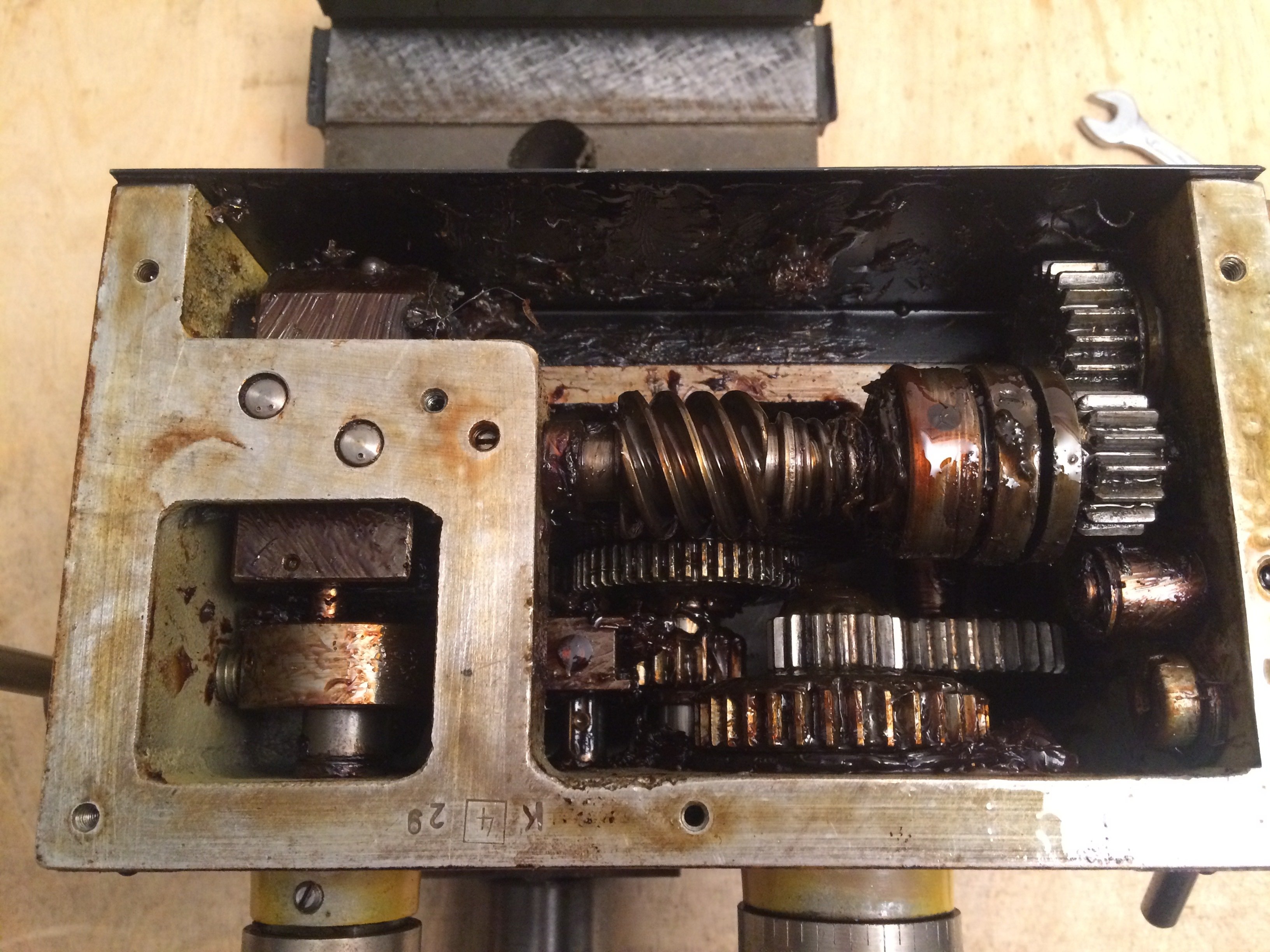
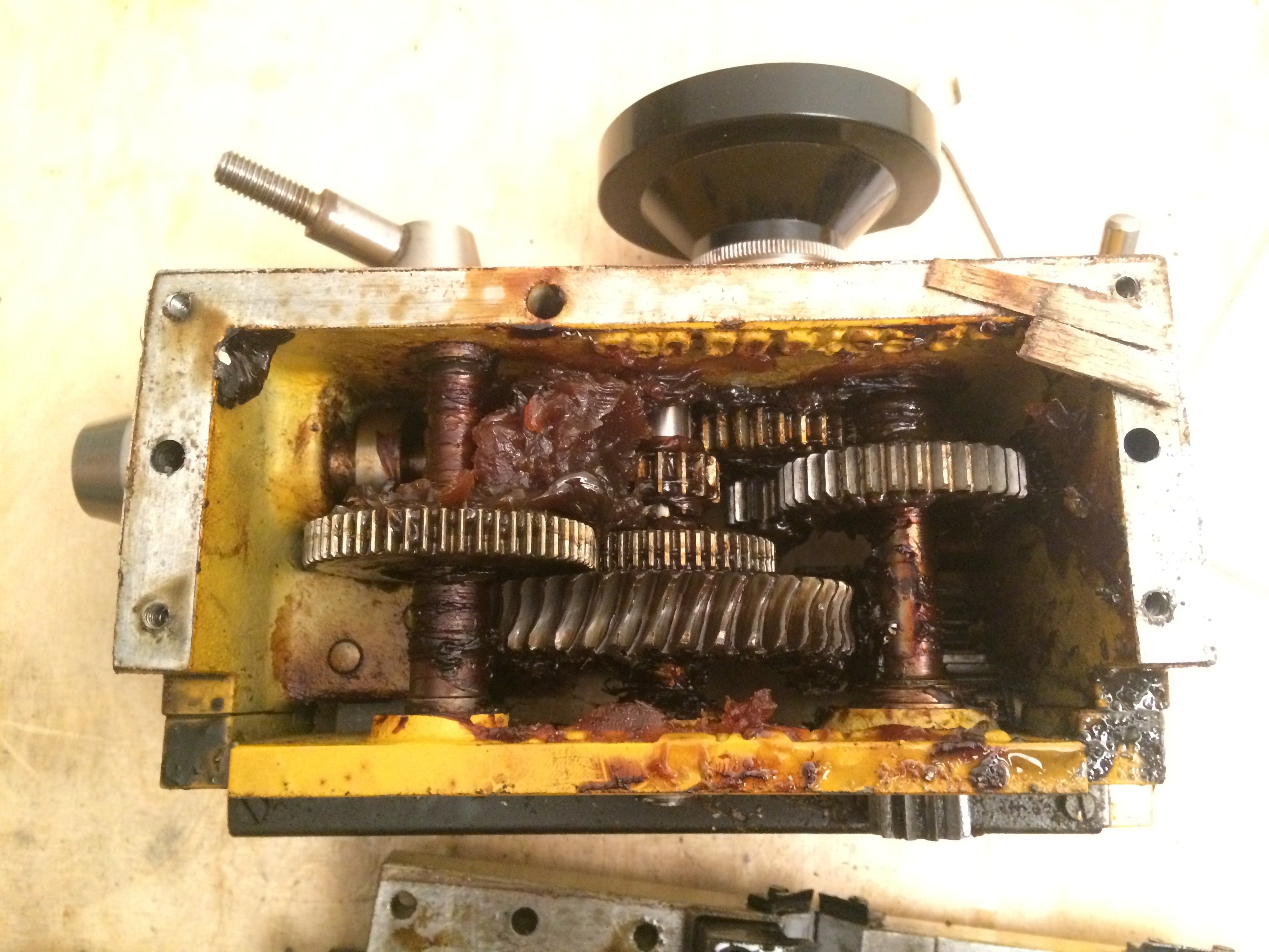
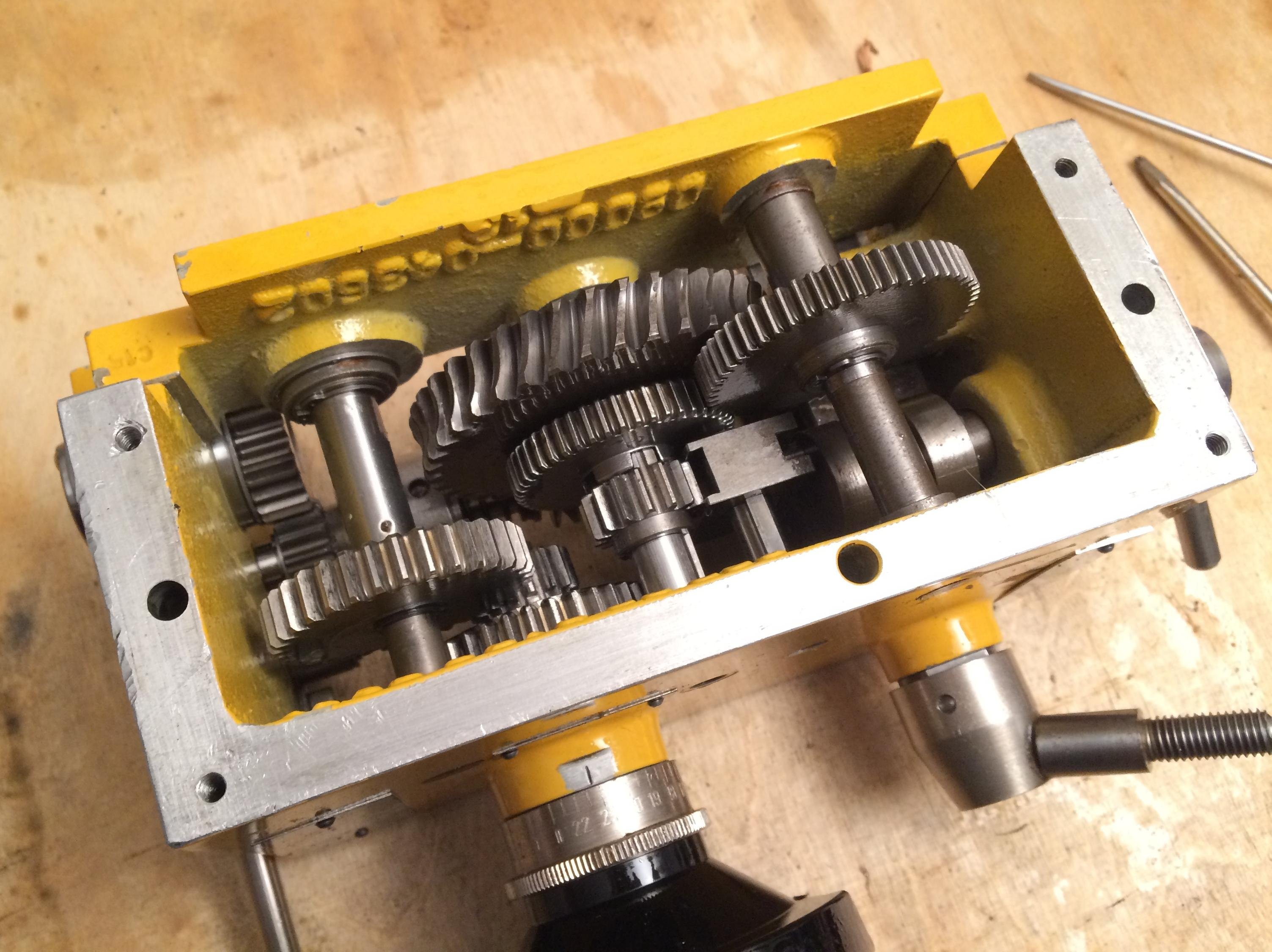
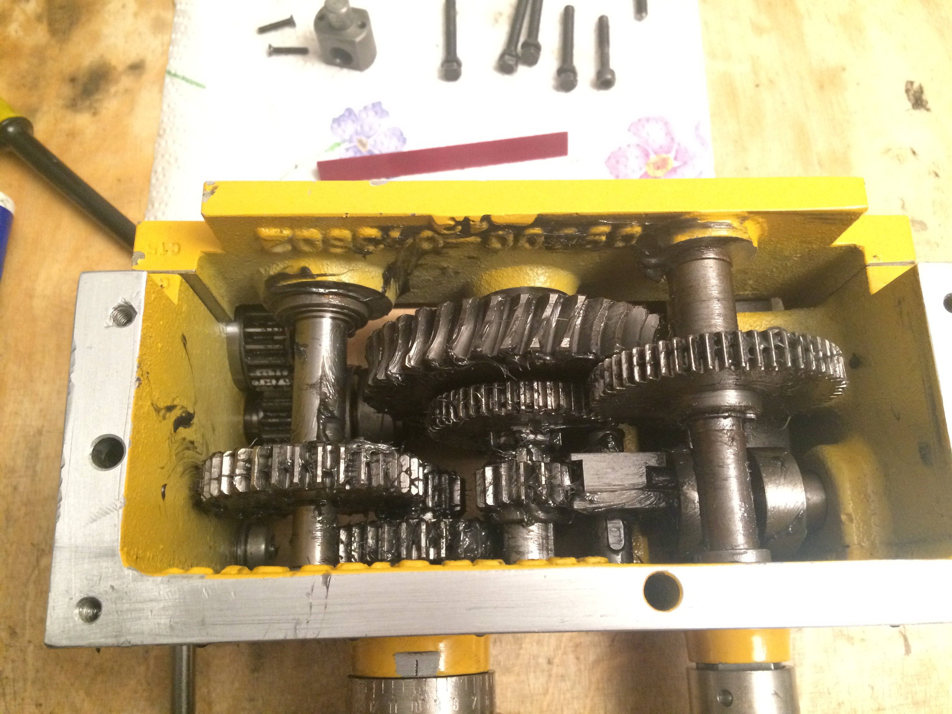
Here’s a look inside the headstock:
There are also a few downsides to this machine:
- combined leadscrew/feedshaft (one rod for both)
- safety devices (E-stop, chuck guard, change-gear cover switch) all non-functional
- apron full of resinified grease with embedded chips -> blocks under power feed
- handles on the saddle handwheel and cross-feed broken off
- handwheel dials that look stunningly cheap
- saddle handwheel feed: 22.5 mm per revolution (WTF???)
- tailstock locked by a nut, not a lever
- carriage clamp located on the underside of the rear way -> awkward to reach
- single-phase AC motor with start cap and centrifugal switch -> “rough” running, slams in hard at switch-on
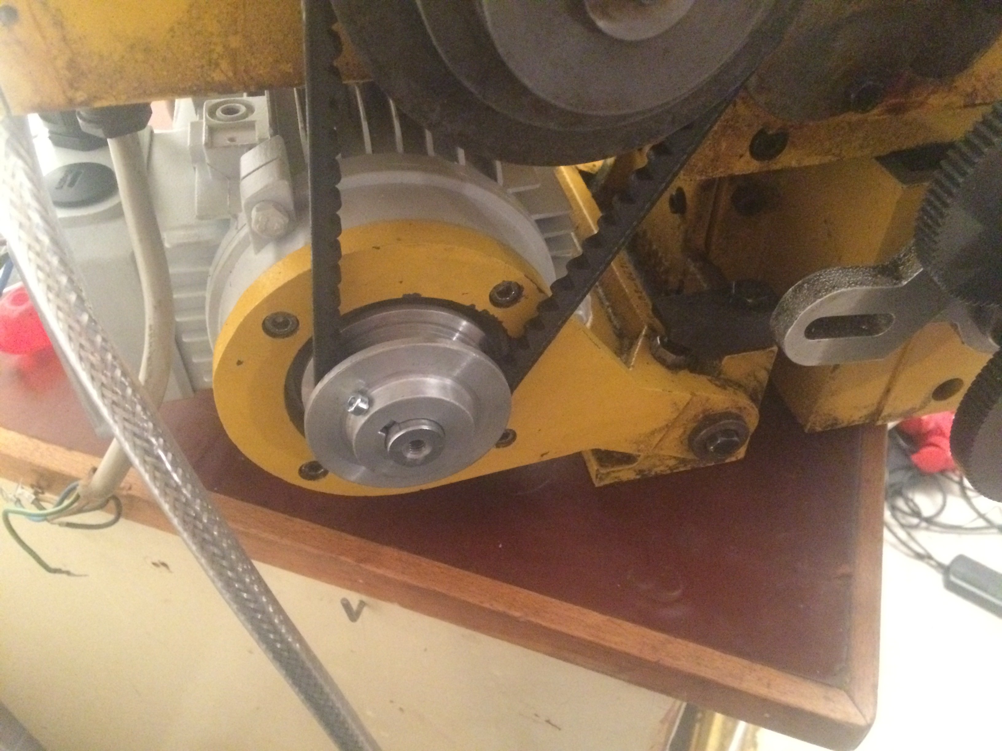
As a first measure the machine was relieved of the worst of the dirt and the V-belt was replaced. An XPZ-587 fits well and runs nice and quietly.
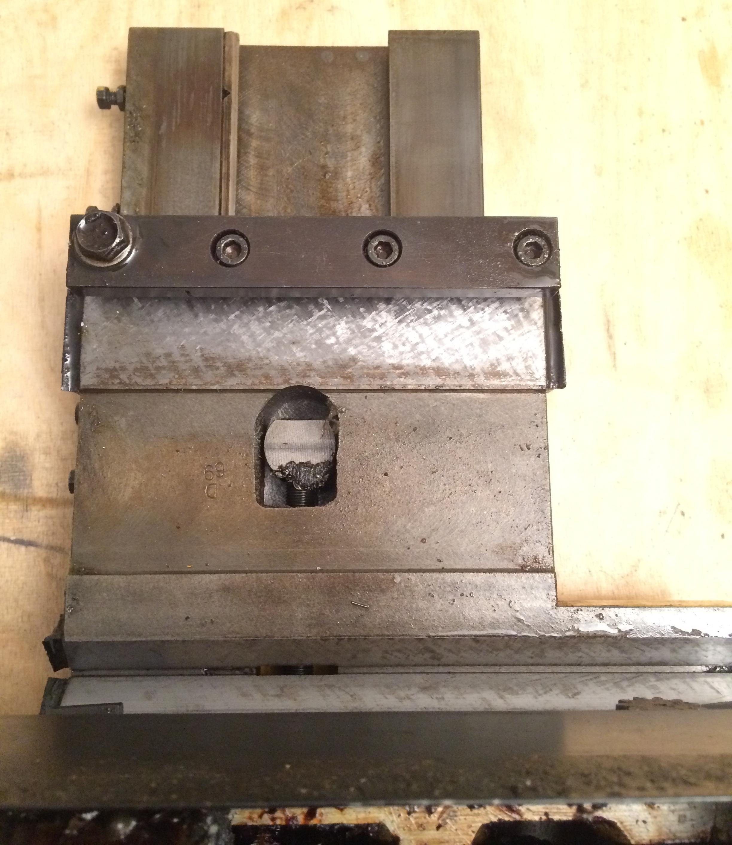
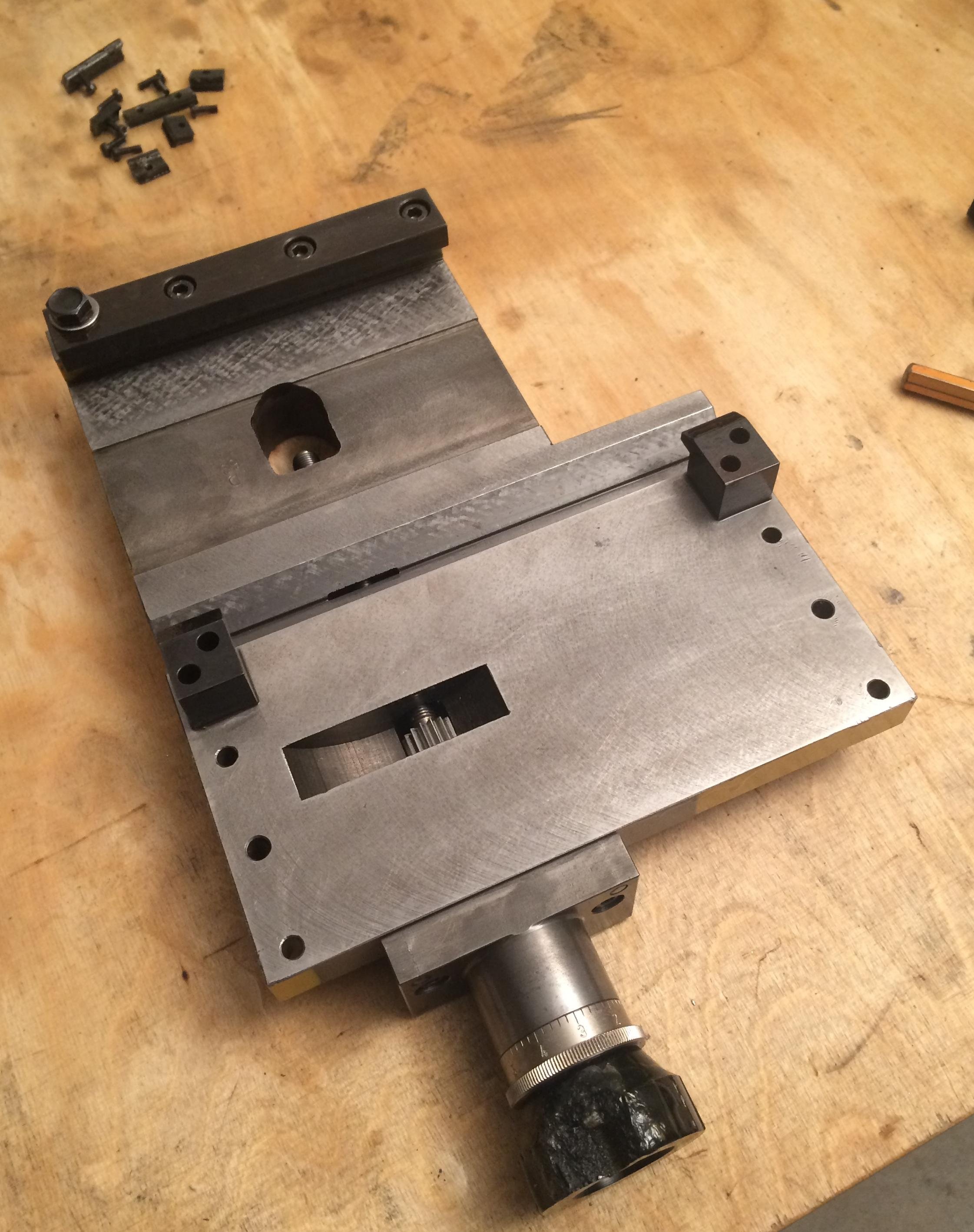
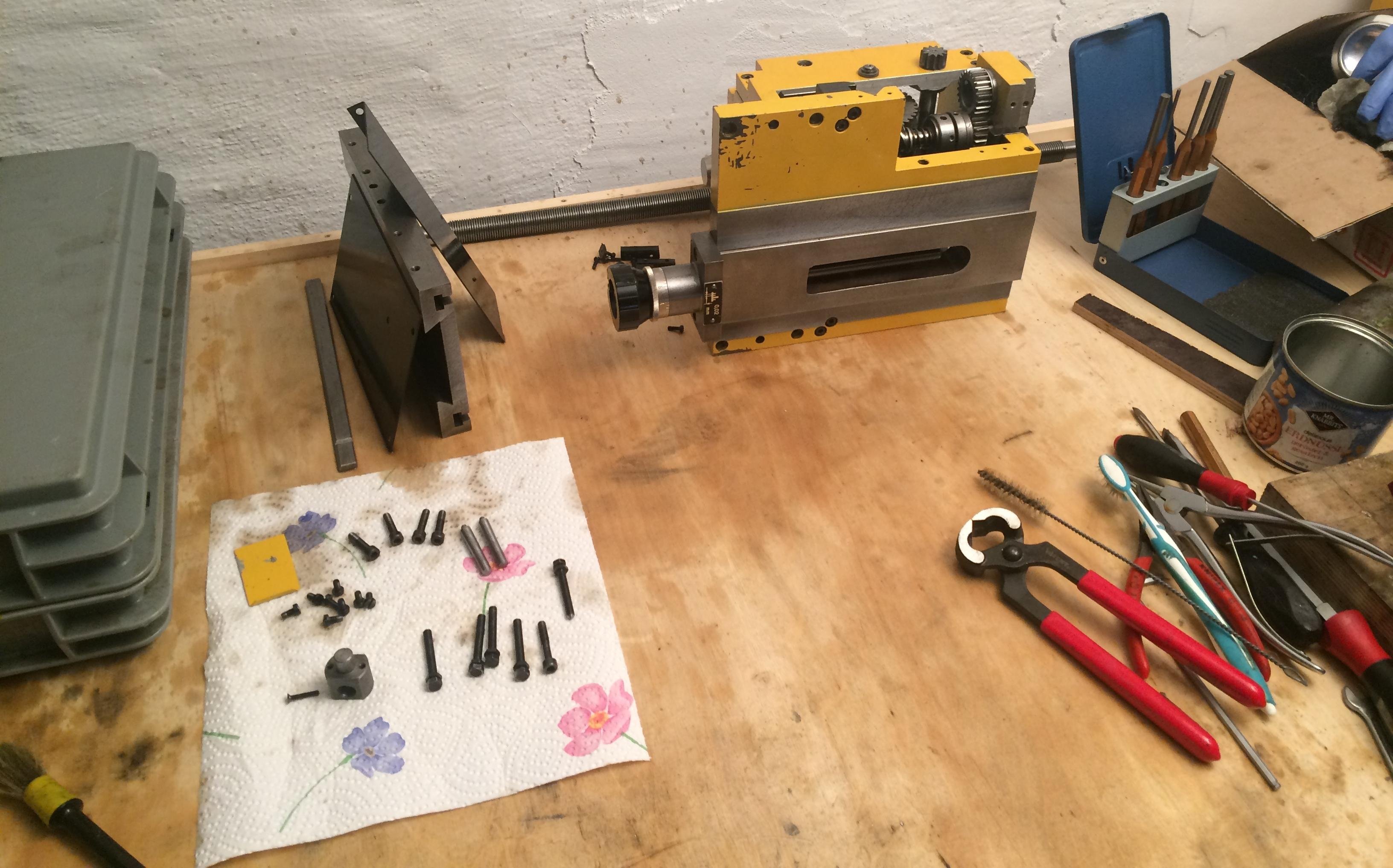
For transport I had taken the saddle off, so I can present a “look up the skirt”:
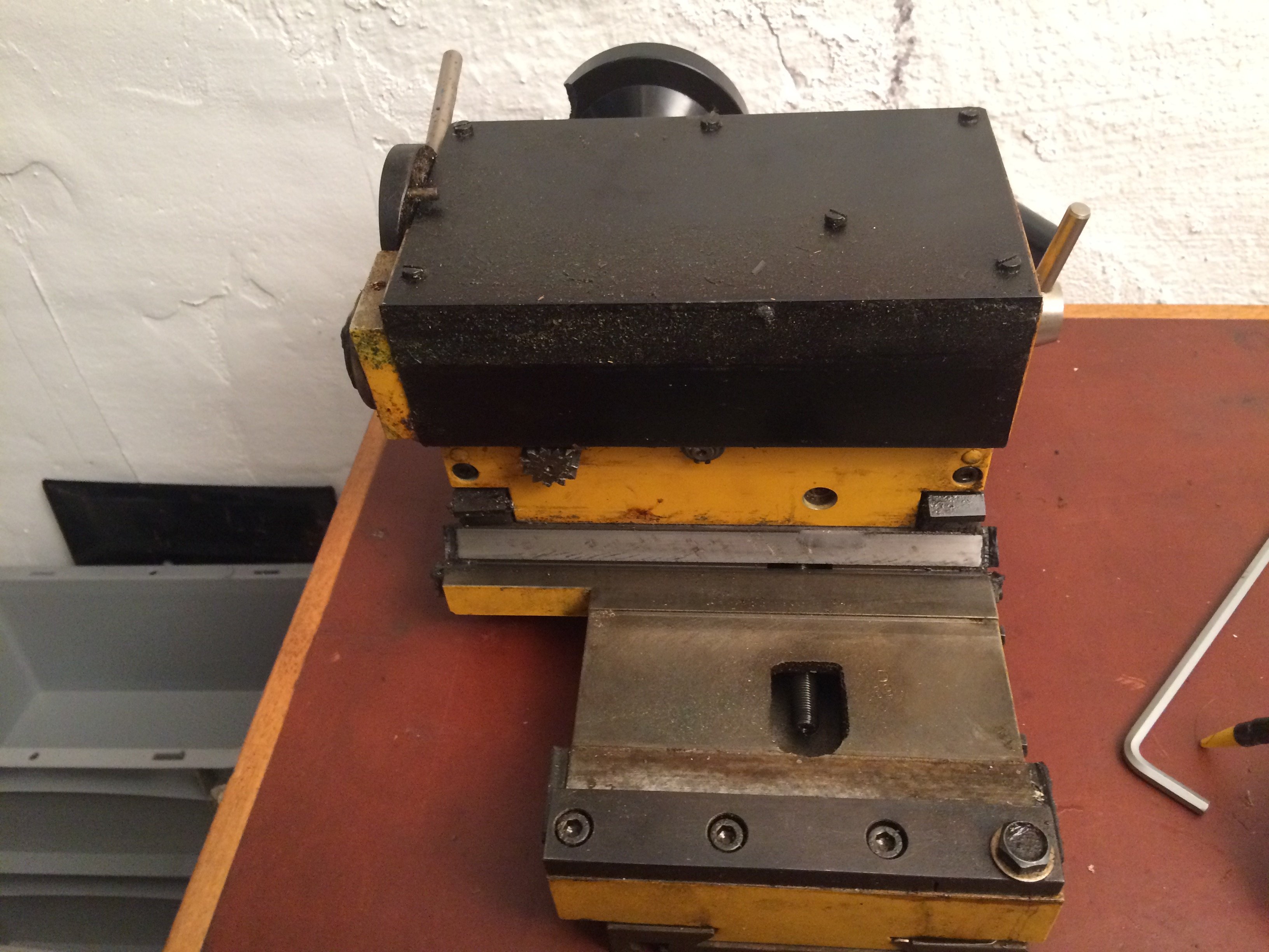
You can see the saddle clamping screw at the front right, the clutch lever for the feed-rod function at the top left, and the switch between longitudinal and cross feed at the top right. The ways are in pretty good shape. The scraping pattern on the front prismatic way under the saddle has been worn off, but the saddle still sits on the bed with very little clearance. That, in turn, means putting the saddle back on the bed elicits some choice expletives, because the slightest mis-positioning makes it bind heavily and you have to be very careful and deliberate.
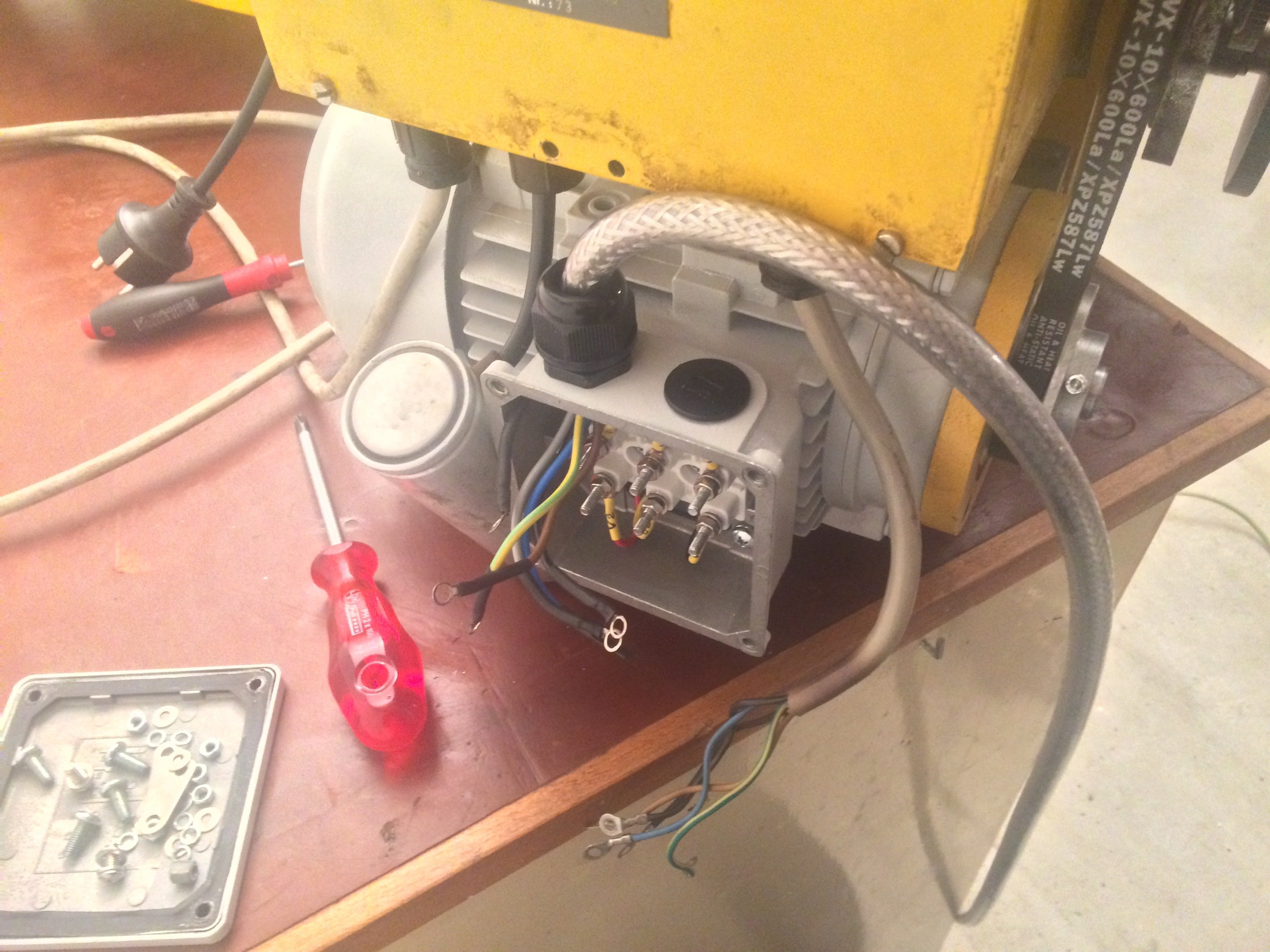
As the next order of business – and something I had firmly committed to at purchase – I planned to fit a three-phase motor with a VFD. It’s again a 1500 rpm / 0.55 kW motor. For the VFD I was able to pick up a Siemens MicroMaster 440 at 0.75 kW. Pleasantly, Saupe used a motor with a standard mounting pattern; unfortunately the original motor’s shaft is 23 mm, while the new standard motor’s shaft is 19 mm. So, using the original motor, I bored an existing aluminium pulley out to 19 mm and am using that until I get around to fitting the old (three-groove) pulley with a new hub.
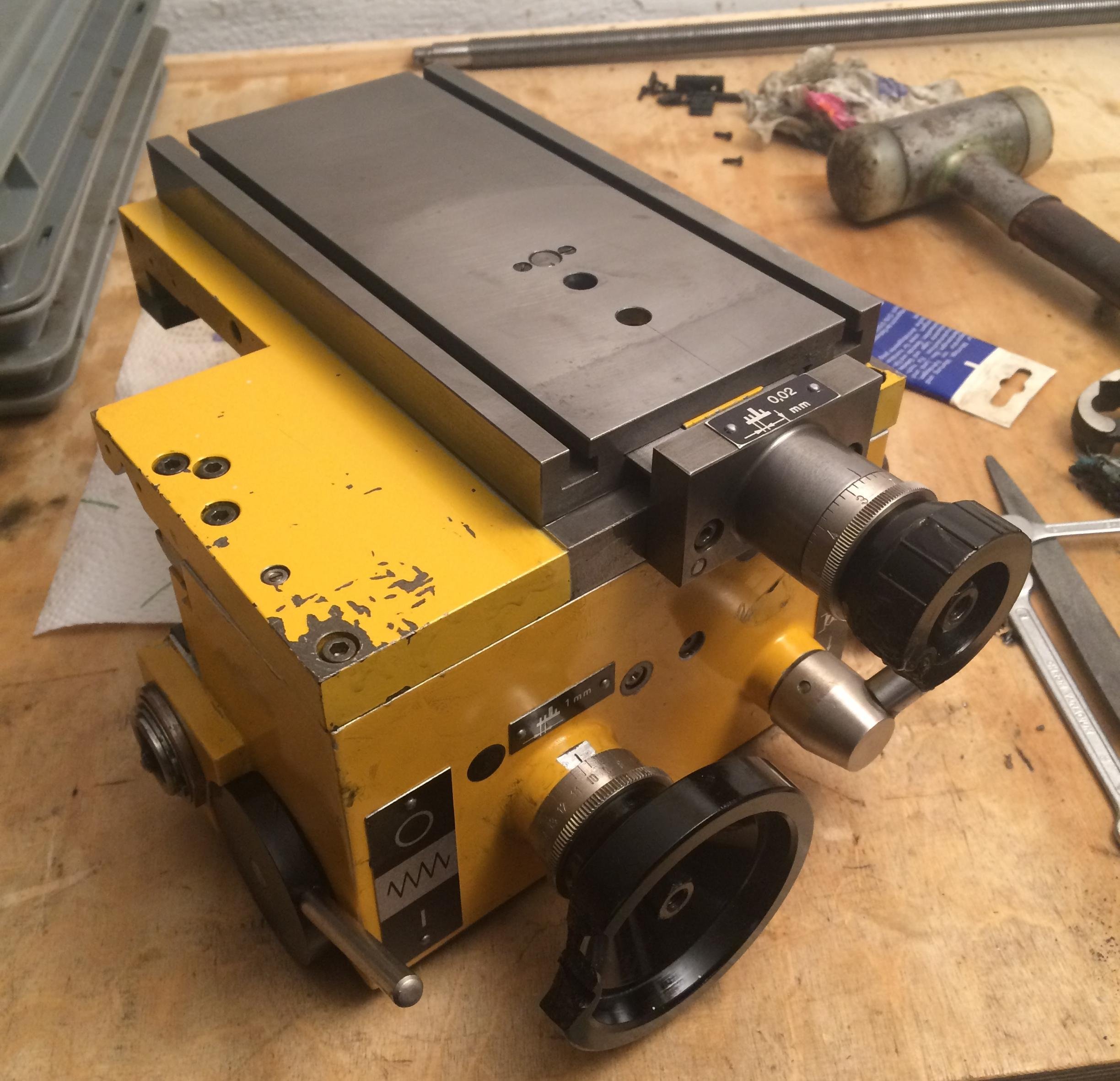
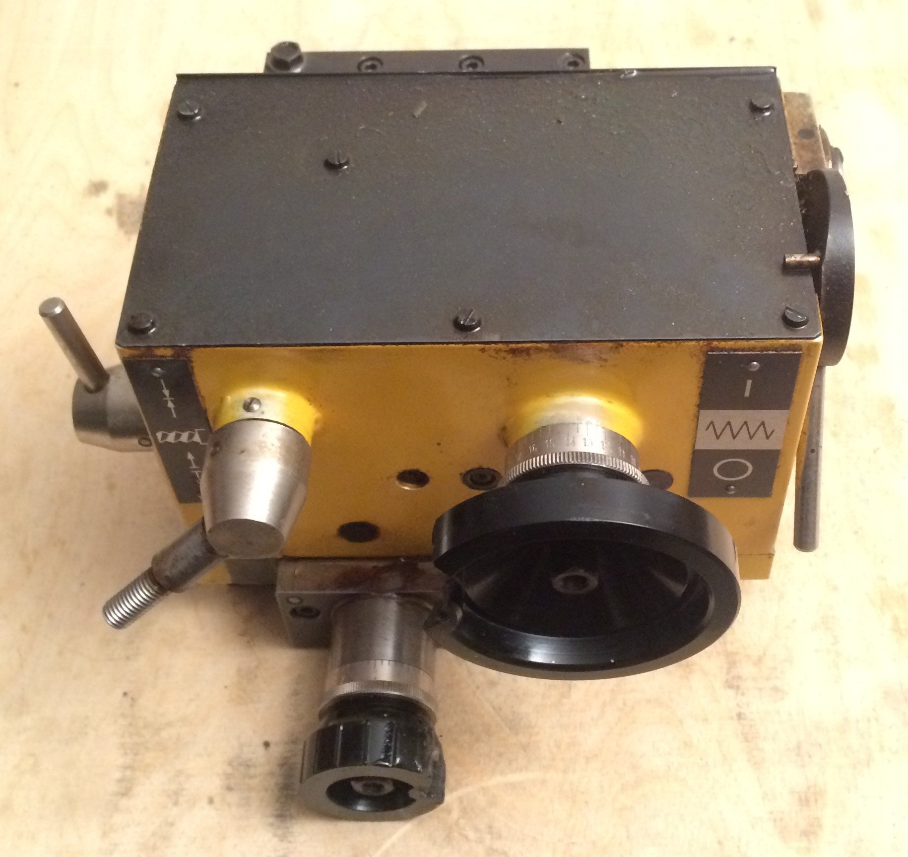
Another peculiarity of the machine is the small box at the front-left under the headstock, which houses an (open-topped!) two-step gearbox for the feed, plus the main switch and the E-stop button:
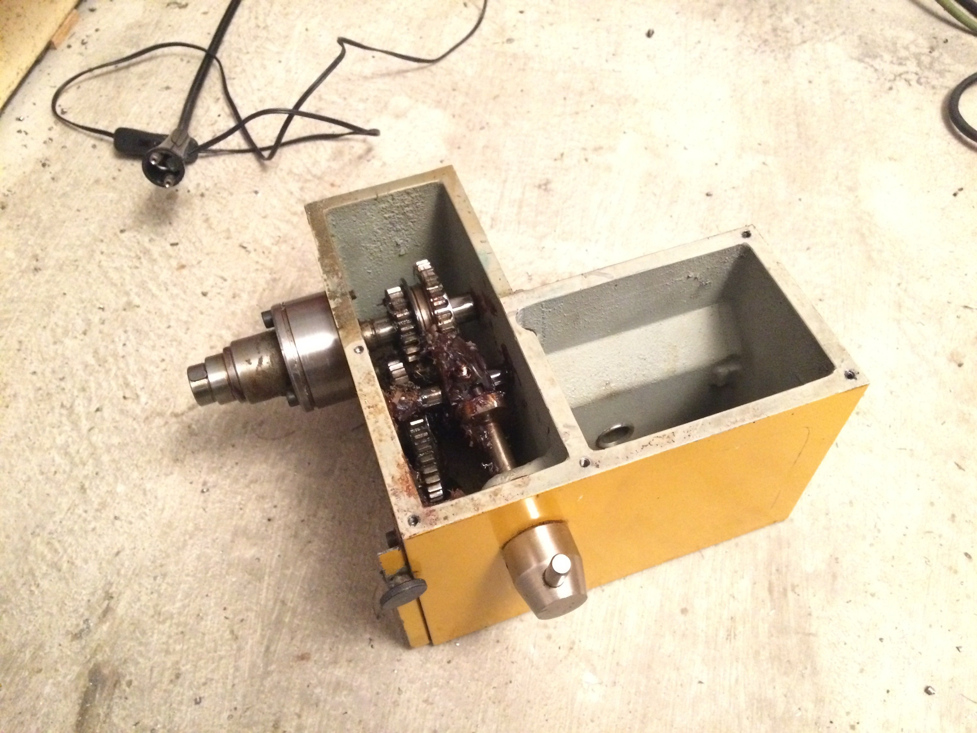
This box is screwed to the left side of the bed:
I’m strongly tempted to design a proper feed gearbox here, to get rid of the tedious change-gear shuffling.
A Robling 800 Stfl., which I once called my own in a previous workshop, spoiled me in this respect with the following table:
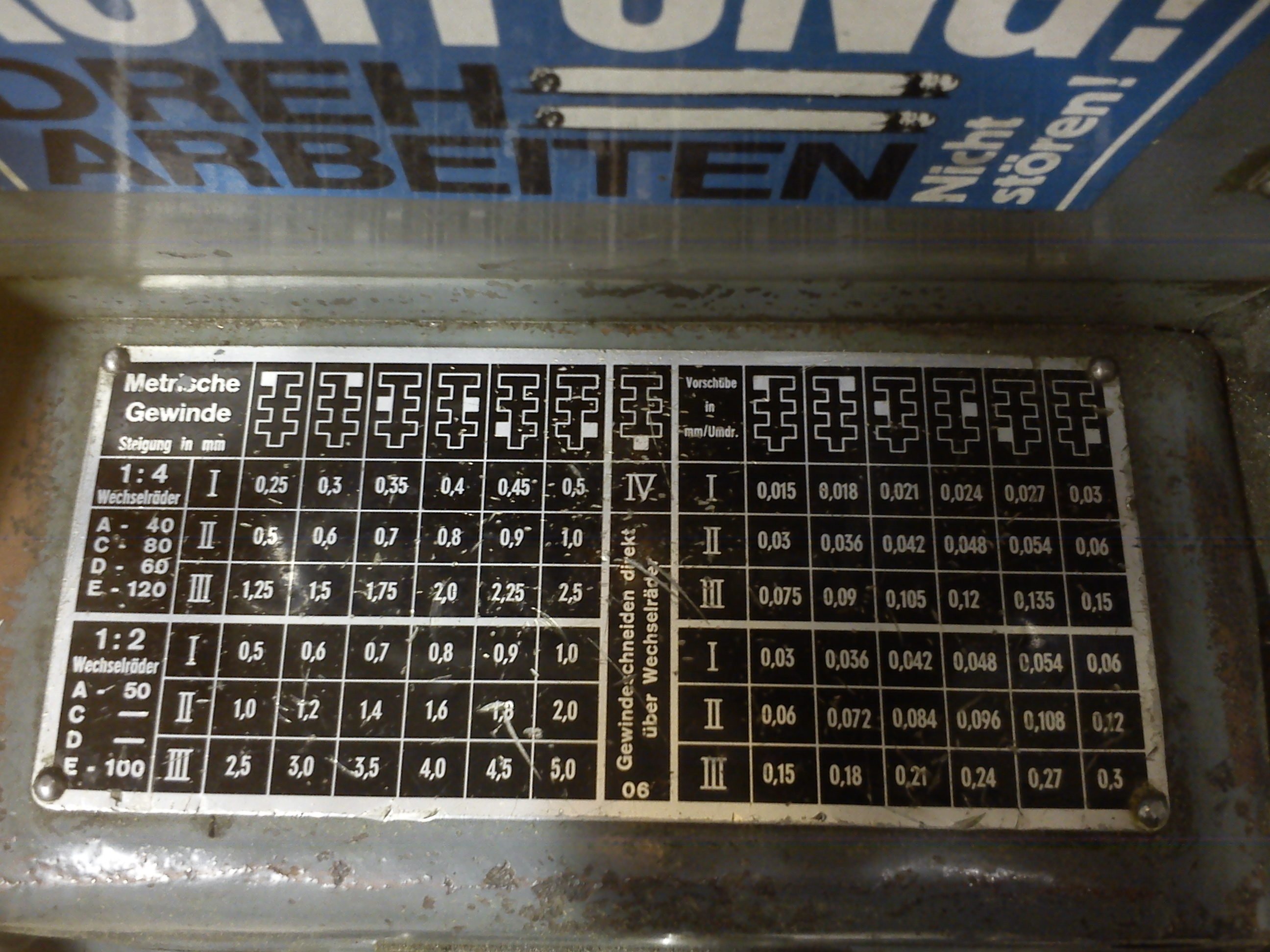
The frequently-needed metric thread pitches and a sensibly-graduated feed range all show up in a 3x6 table – a dream…
The work I’ve planned for myself over the coming months so far:
- Fit a known quick-change tool post with 40 indexed positions in size “A”. I’ll probably have to replace the compound slide with a riser block, because the centre height over the compound is only 16 mm, which – combined with the thickness of the lower flange of the tool-holder cassette – would leave only 8 mm for tools.
- Build an electrical cabinet for the VFD; mount a speed-control pot on the machine.
- Fit a hub on the old pulley so I can use all belt steps with the new motor. At the moment I can only use the slowest pulley step. For high spindle speeds I’d have to spin the three-phase motor uncomfortably fast.
- New handwheels for tailstock, compound, saddle and cross-feed with proper handles (no plastic, above all!) and nice dial wheels.
- Disassemble, clean and possibly repair the apron.
- Final fit-up of an already-prepared faceplate to the KK3 spindle nose.
- Tailstock clamp like Stefan’s ukrodreh (see Post #71479), possibly even a conversion to a rack-driven quill…
- Make the saddle clamp accessible from above.
- Tailstock clamp on the bed via hand lever.
- Grease nipples and oil grooves in the saddle and cross slide.
- New felt wipers for the saddle ways instead of the dainty plastic pieces.
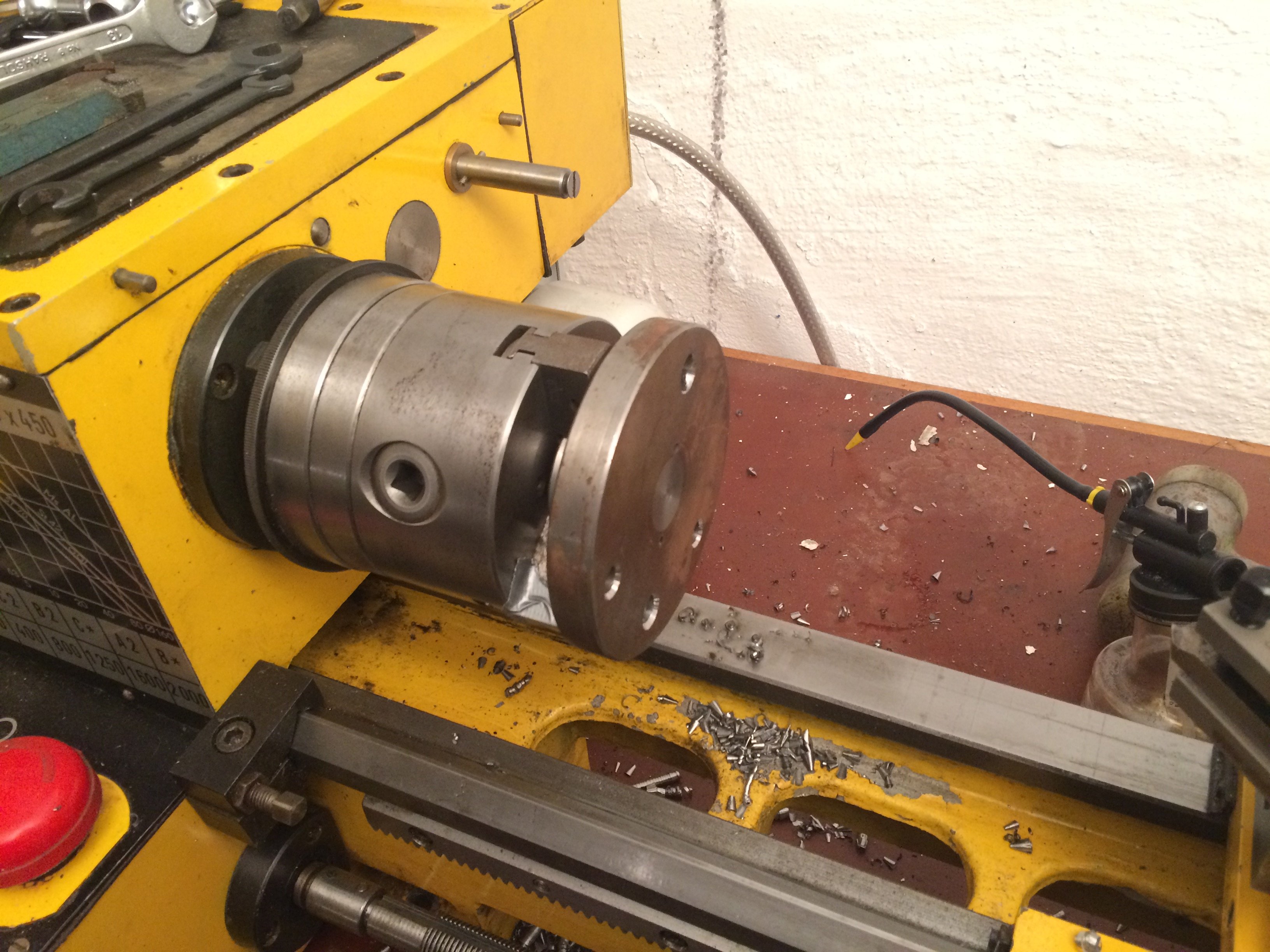
Fitting a faceplate #
Continuing with the fitting of an already-prepared faceplate. Specifically, only the short taper still needed turning, since I’ve had this faceplate lying around for years and only with the DLZ180x450 do I have a suitable machine to mount it on.
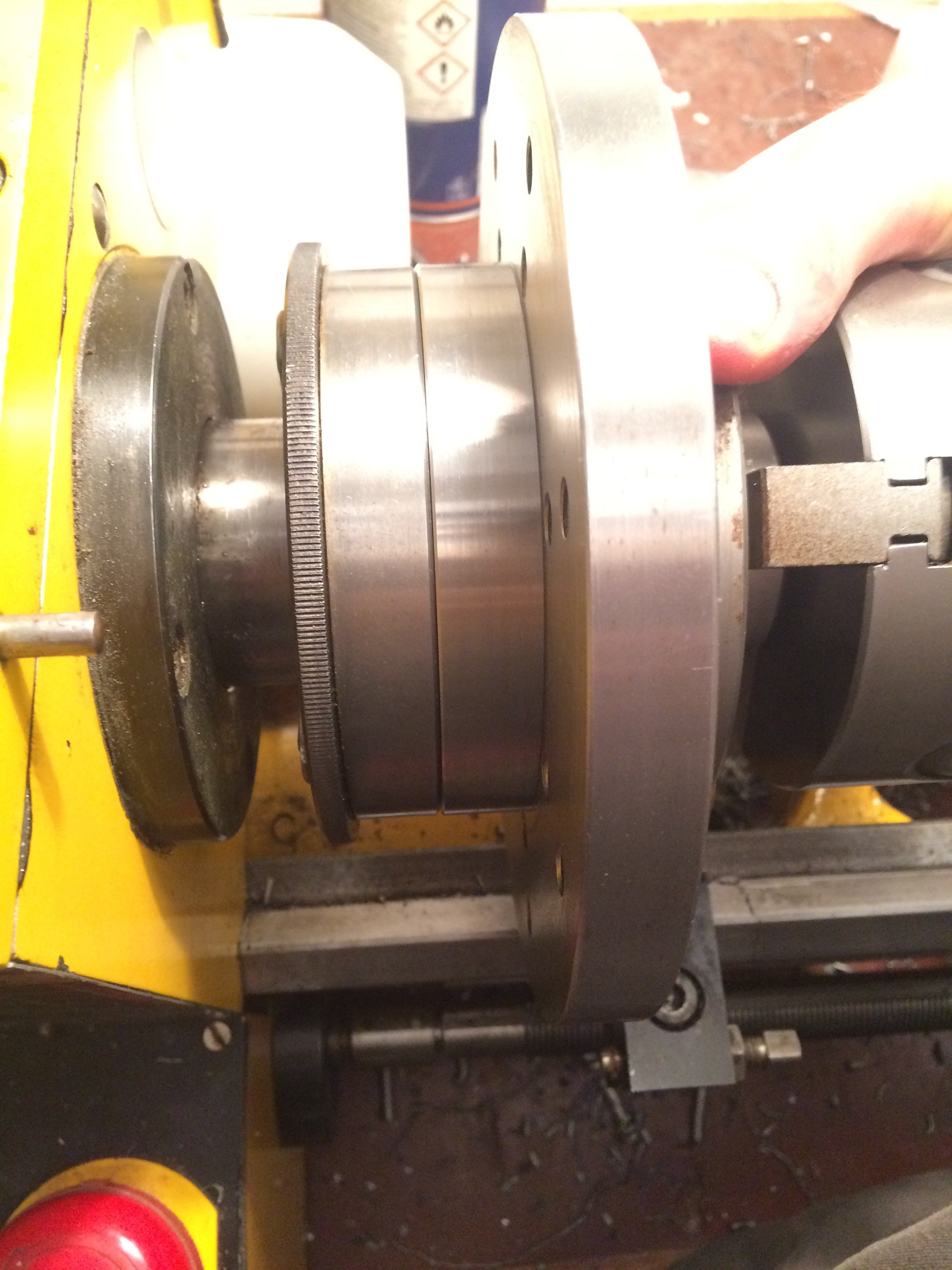
Here’s a preview of the end result:
I had once rescued the rough disc for the faceplate from the scrap pile and quickly added the holes and threads. Then I devoted myself to my studies for a few years and only now have time again every now and then to do some tinkering. The disc was faced on the back side on another machine (hi Hartmut ;-) ) and a 100 mm OD ring screwed centrally to it. In that ring – into which I now only had to turn the short taper – three M10 threads for the studs to retain the KK adapter were already prepared.
So the starting point was: I had a lathe with a 3-jaw chuck and had to clamp the faceplate “backwards” to turn the KK. A part from the scrap box helped here – once a holder for a 3-jaw chuck on a rotary table; a steel disc with an aluminium boss screwed onto its centre:
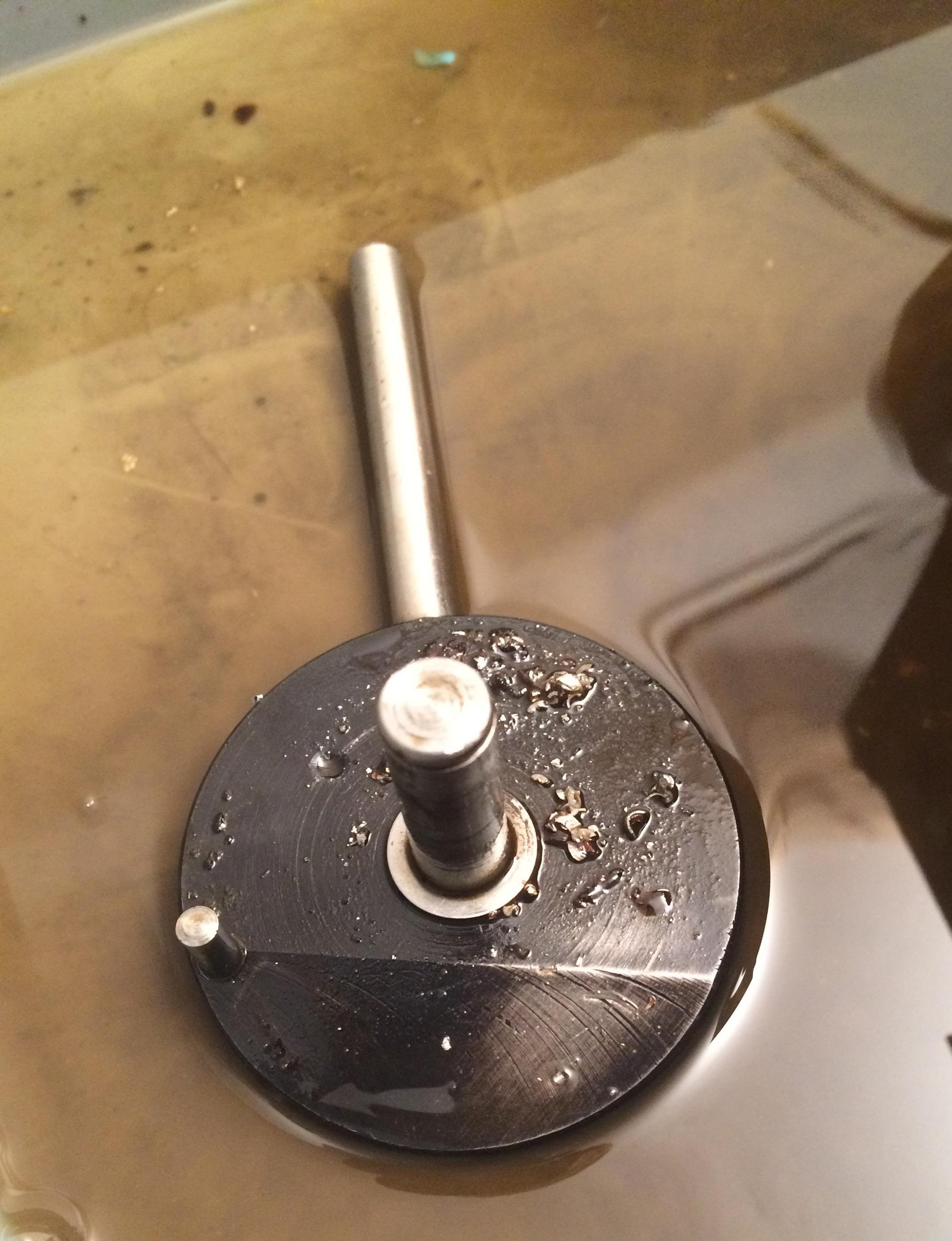
This part was then faced by hand with a wide-cutter finishing tool (automatic feed wasn’t yet working again, see below):
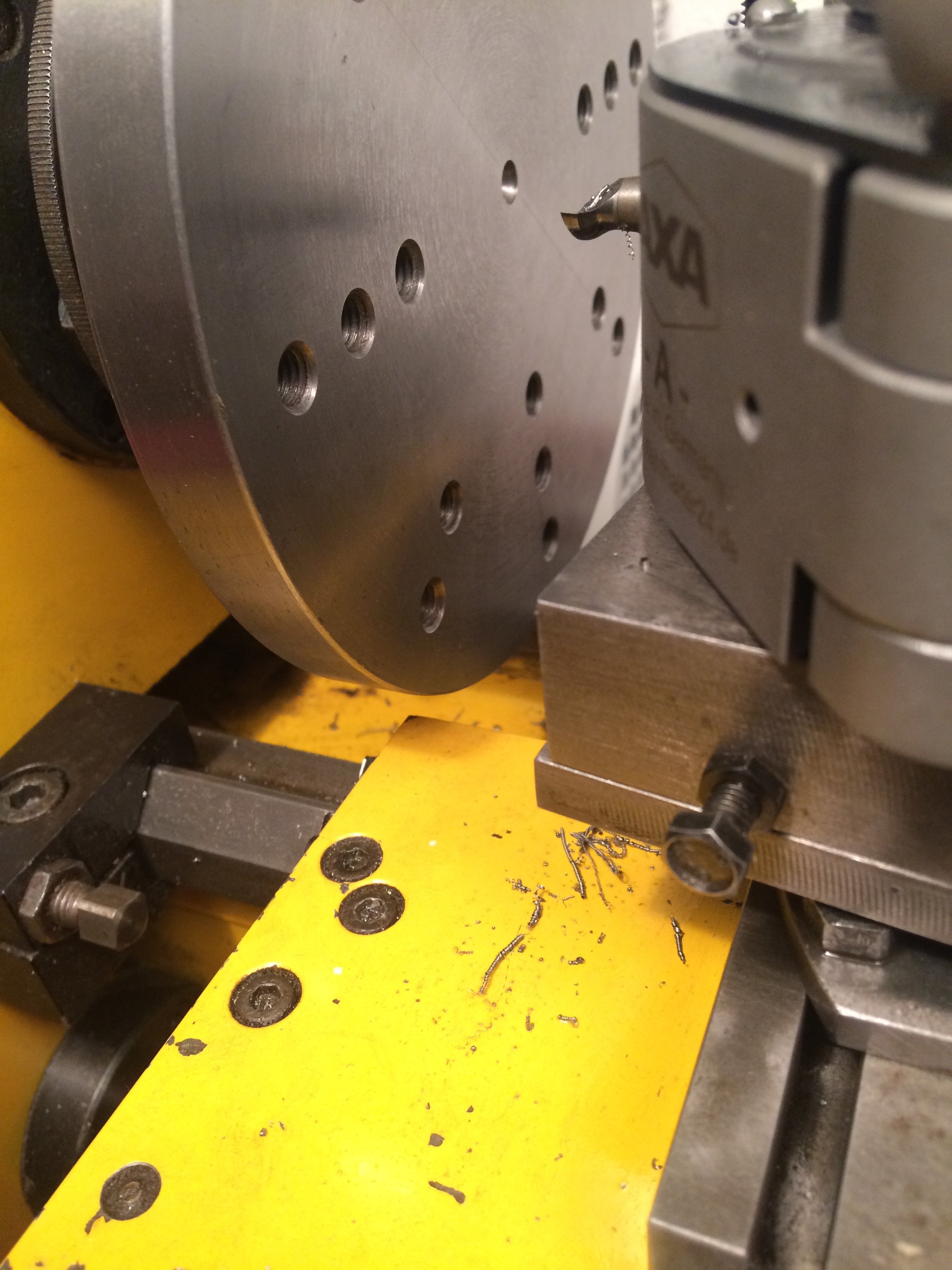
Here’s a detail view of the cutting tool:
The surface came out reasonably well, and with a 1/100 mm test indicator I couldn’t find any unevenness; that should also be the case anyway as long as you don’t disturb the setup. The faceplate could then be clamped against the part still in the chuck using two M8 screws. The compound was set to the taper angle of the KK in advance.
The short taper could now be turned. The hard part is normally not to let the taper diameter come out too large, so that there’s a little preload when the flange is screwed onto the spindle nose. The procedure I have settled on, which has now produced reproducibly good results several times, is the following.
First, with the saddle locked, you turn the taper roughly to the point where it’s about half-way onto the spindle nose. Normally it’s enough to take the diameter with a calliper and compare with the inside diameter of the workpiece. At that point you zero the cross slide so that you can crank the compound back to clear and still hit the same diameter. Together with the carriage stop and the cross slide zero, the position of the compound is uniquely defined and reproducible – even if you have to move the cross or saddle in between to test the taper against the spindle nose. The saddle can therefore be moved aside. The 3-jaw is unscrewed from the spindle nose; the workpiece (in this case the boss with the faceplate hanging from it) must under no circumstances slip in the chuck due to a too-rough handling. The just-turned taper is now held by hand against the spindle nose and should slide on about half-way (or as far as you have dared to do “blind”). With gauge blocks, feeler gauges or a calliper, the gap between the spindle nose’s locating face and the planar face of the taper being turned is then measured. The carriage stop has to be shifted toward the headstock by that amount (minus about 5/100 mm). The chuck plus workpiece is then re-mounted, and with a dial indicator in contact, the carriage stop is moved towards the headstock. The cross slide is returned to its zero (mind the backlash!). The compound is now exactly back to the same diameter, but a few millimetres (i.e. by however far you moved the carriage stop) closer to the chuck. The internal taper therefore advances by exactly that distance into the workpiece. If you’re brave you set the carriage stop to the final position right away. The depth of cut can become large enough that the boring bar starts to chatter. Since the cross slide is zeroed at the final position, you can – for the first few roughing cuts – comfortably move the cross toward the centre to reduce depth. The final cut, however, must be made with the saddle against the (shifted) carriage stop and the cross slide at zero.
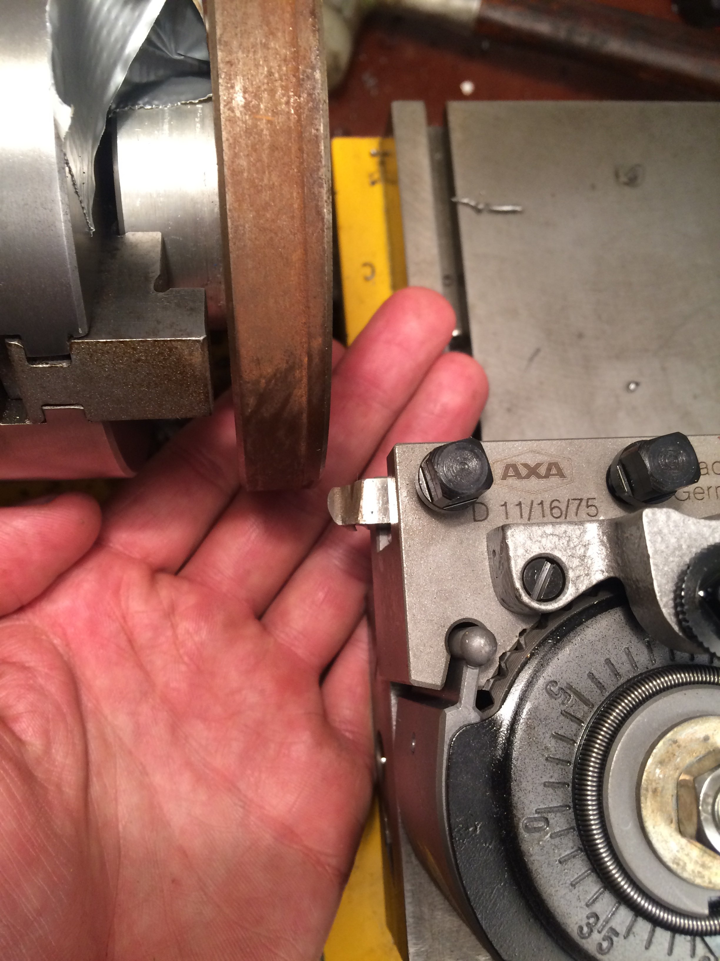
The boring bar was damped against chatter with a wooden wedge:
When everything fits, the just-turned taper goes almost all the way onto the spindle nose, and tightens up far enough when bolted on that it can only be removed with a soft tap of the heel of your hand:
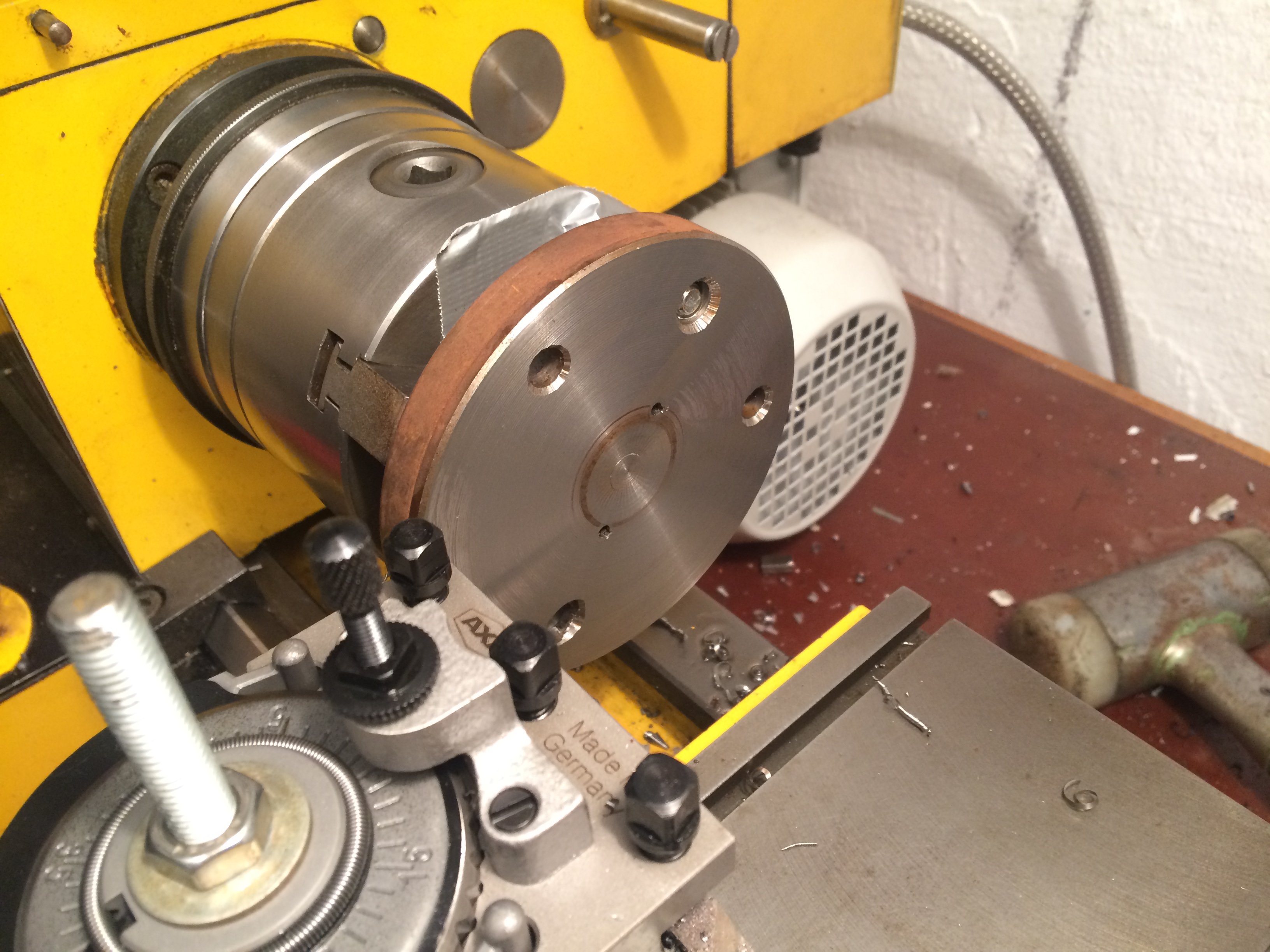
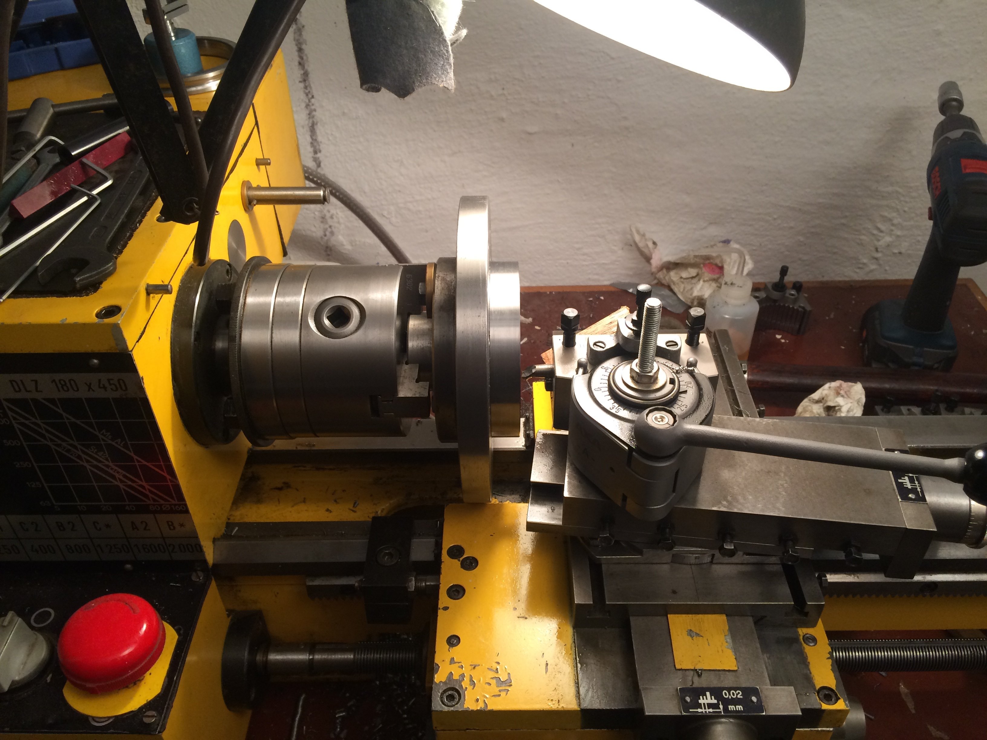
And if you buy the lathe to match the existing faceplate blank, the faceplate fits over the saddle by just a hair:
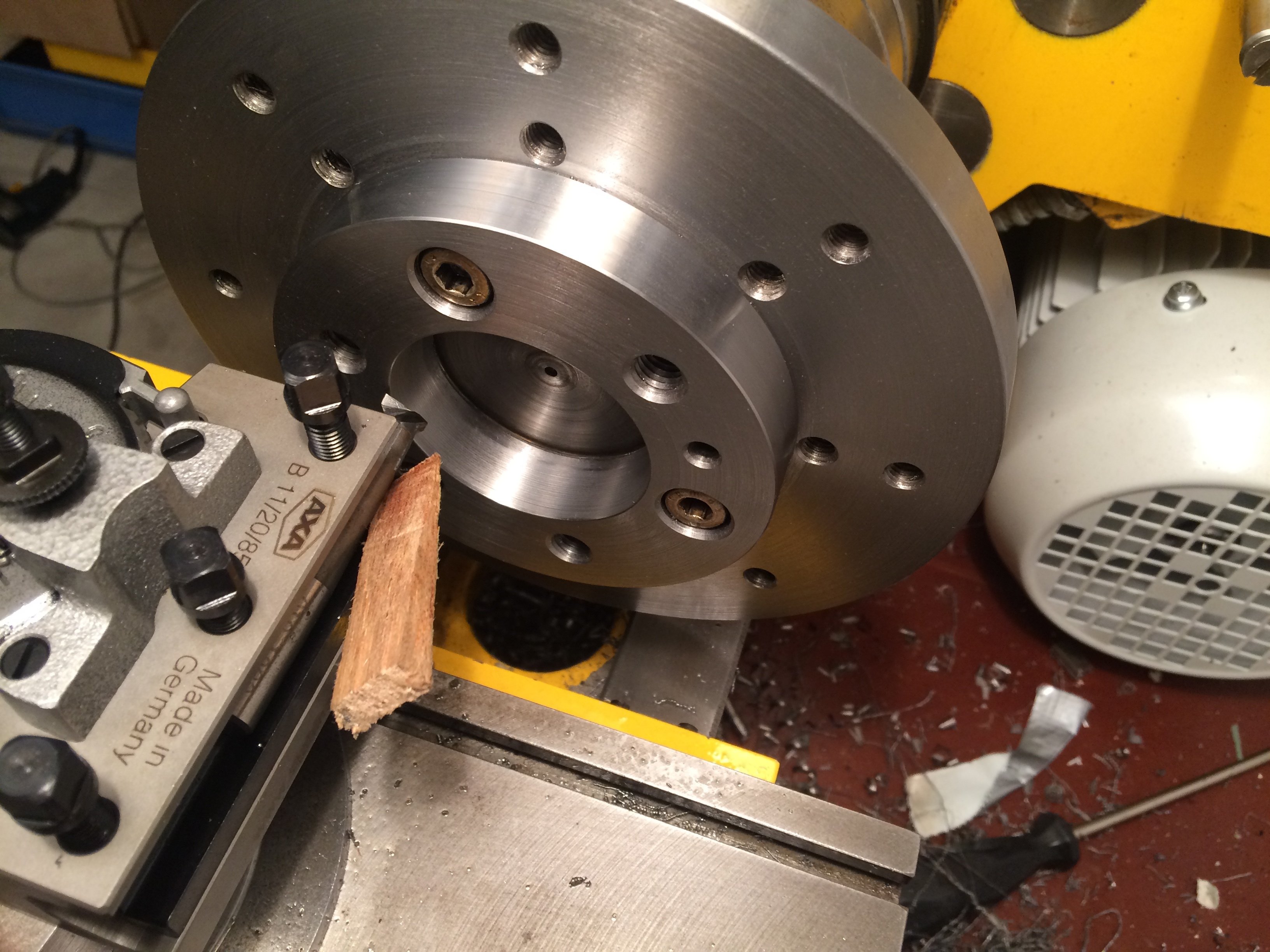
To finish, a picture of the end result. This is what working with it looks like:
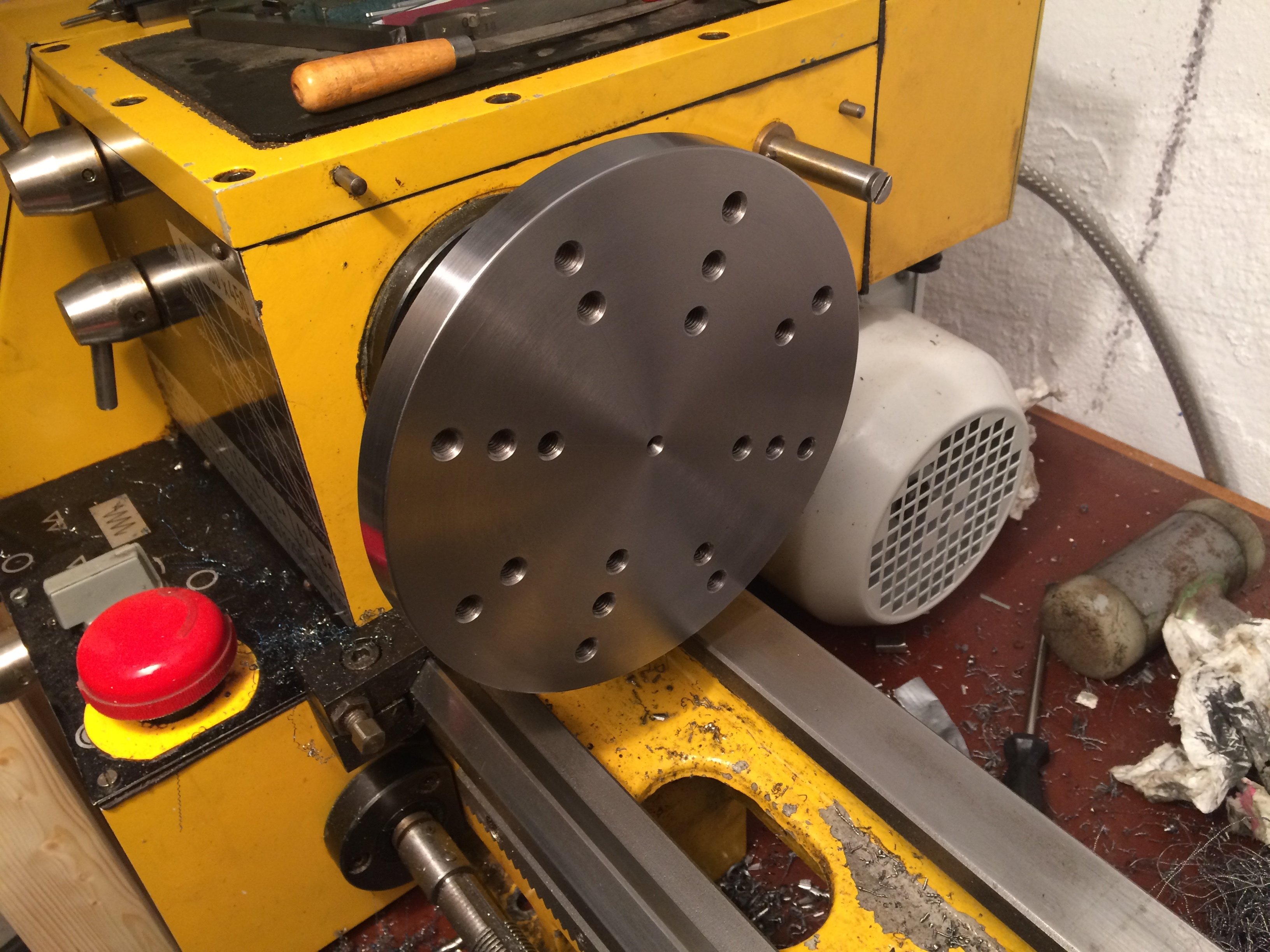
The measured face runout (between the outer bolt circle and the OD) is now about 1/100 mm. The OD was finished in this same setup.
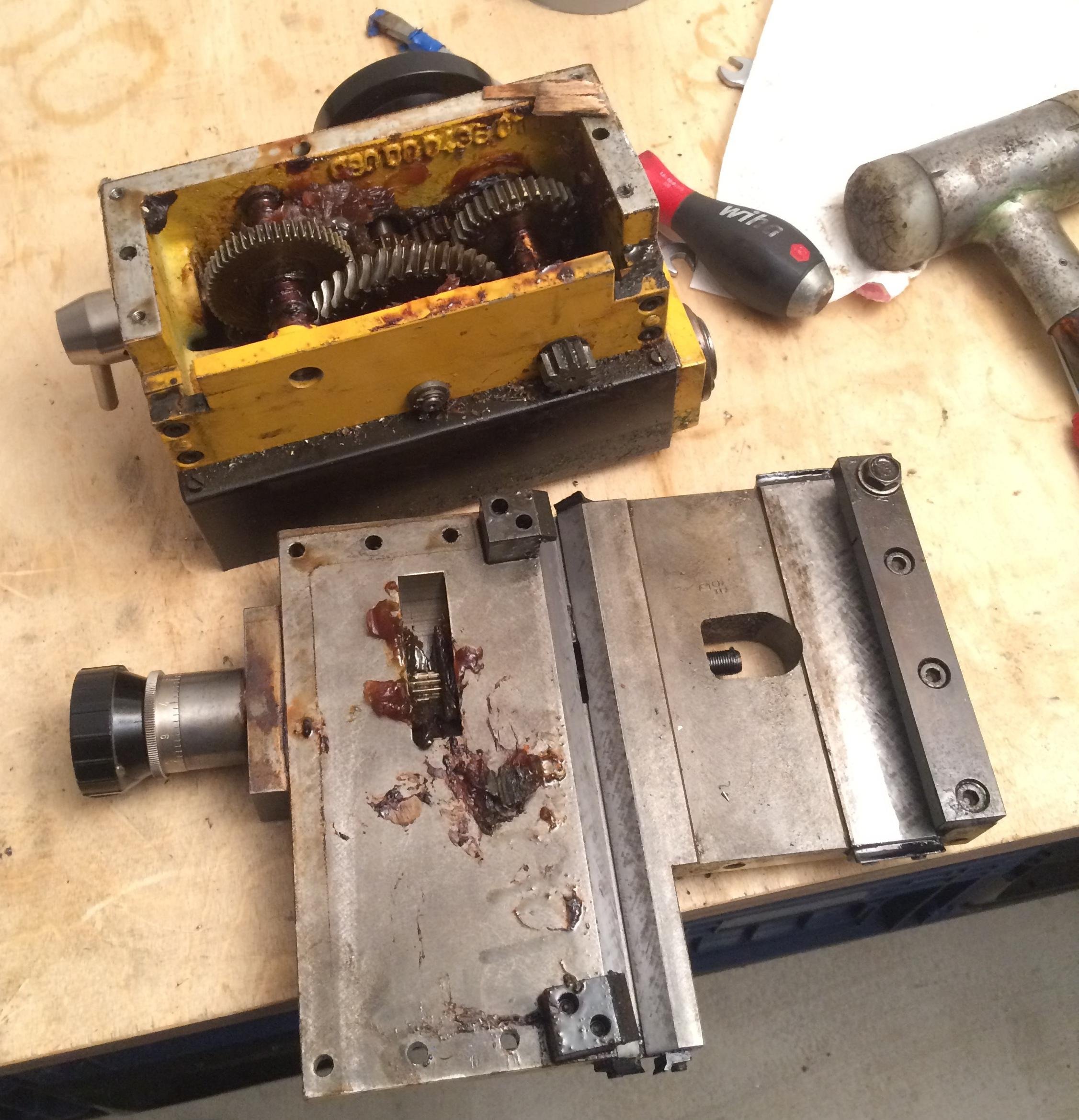
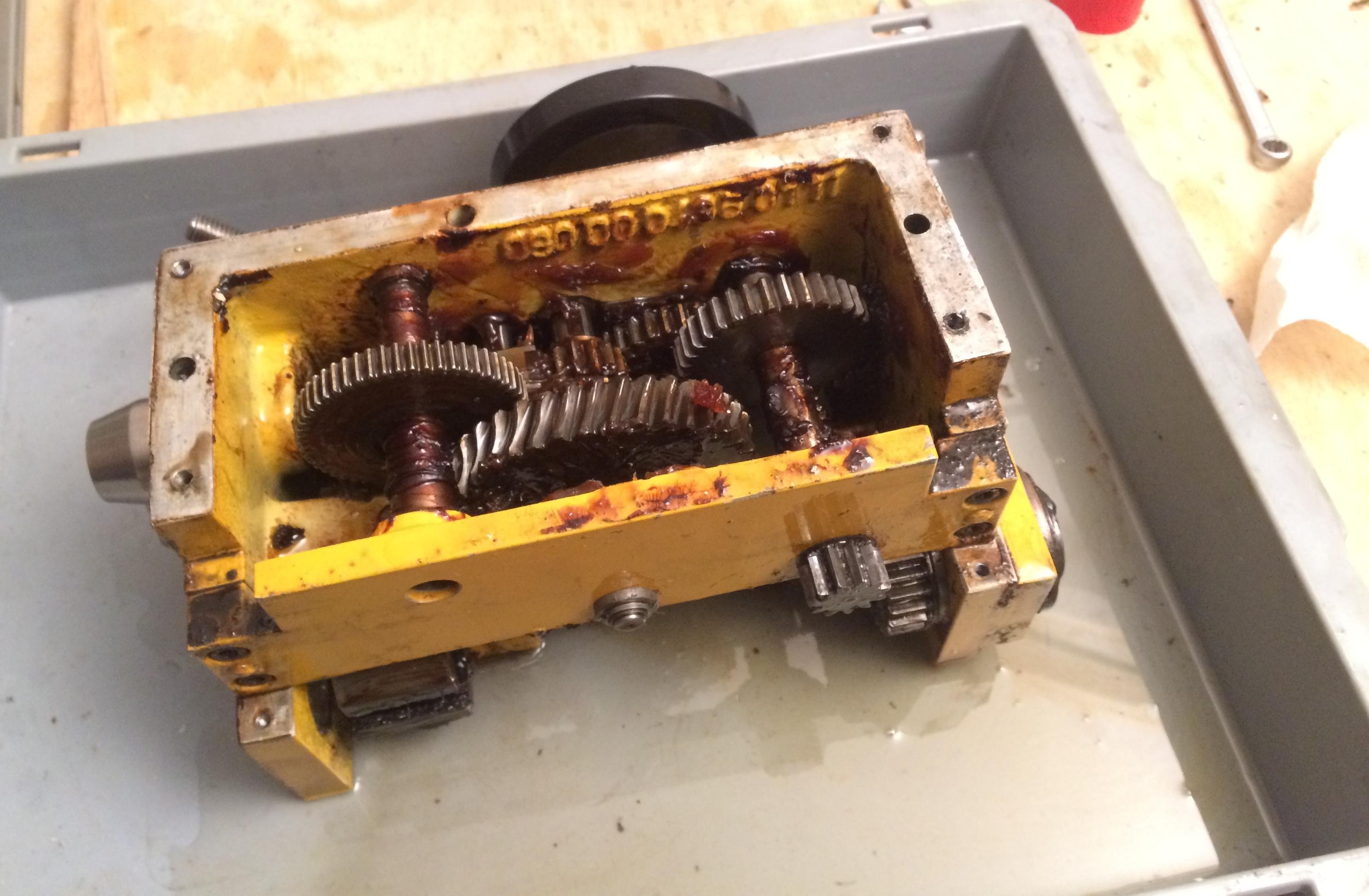
Cleaning the apron #
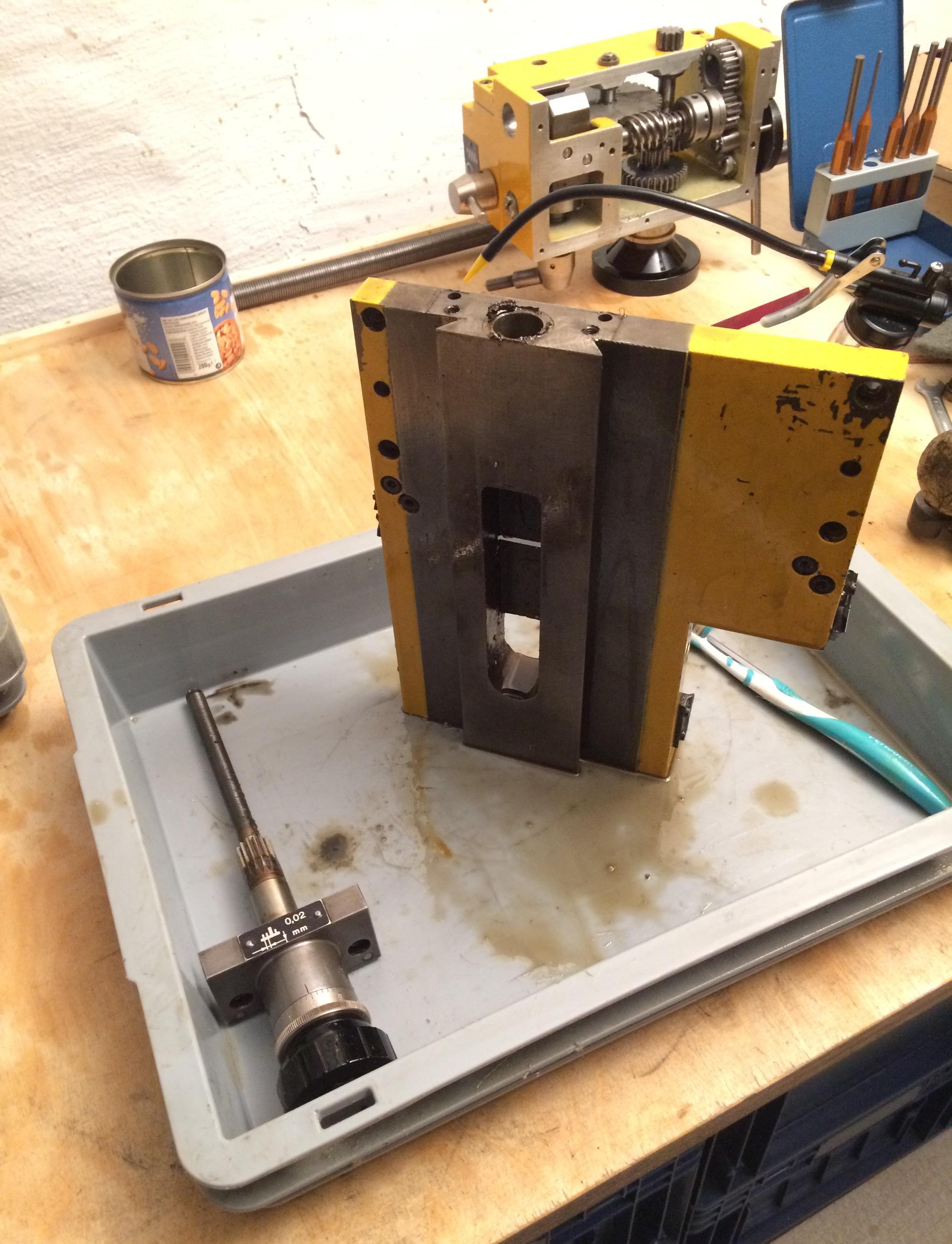
When I bought the machine the feed was sadly non-functional. Specifically, the shear pin on the leadscrew/feedshaft had sheared and something in the apron was binding. Onto the operating table with the patient:
We start on the bottom, where a sheet-metal cover initially obscures the view:
Once that comes off, the horror reveals itself in all its glory:
A small side note: the saddle’s prismatic way at the front has lost most of its scraping pattern; the rear side still looks reasonably OK:
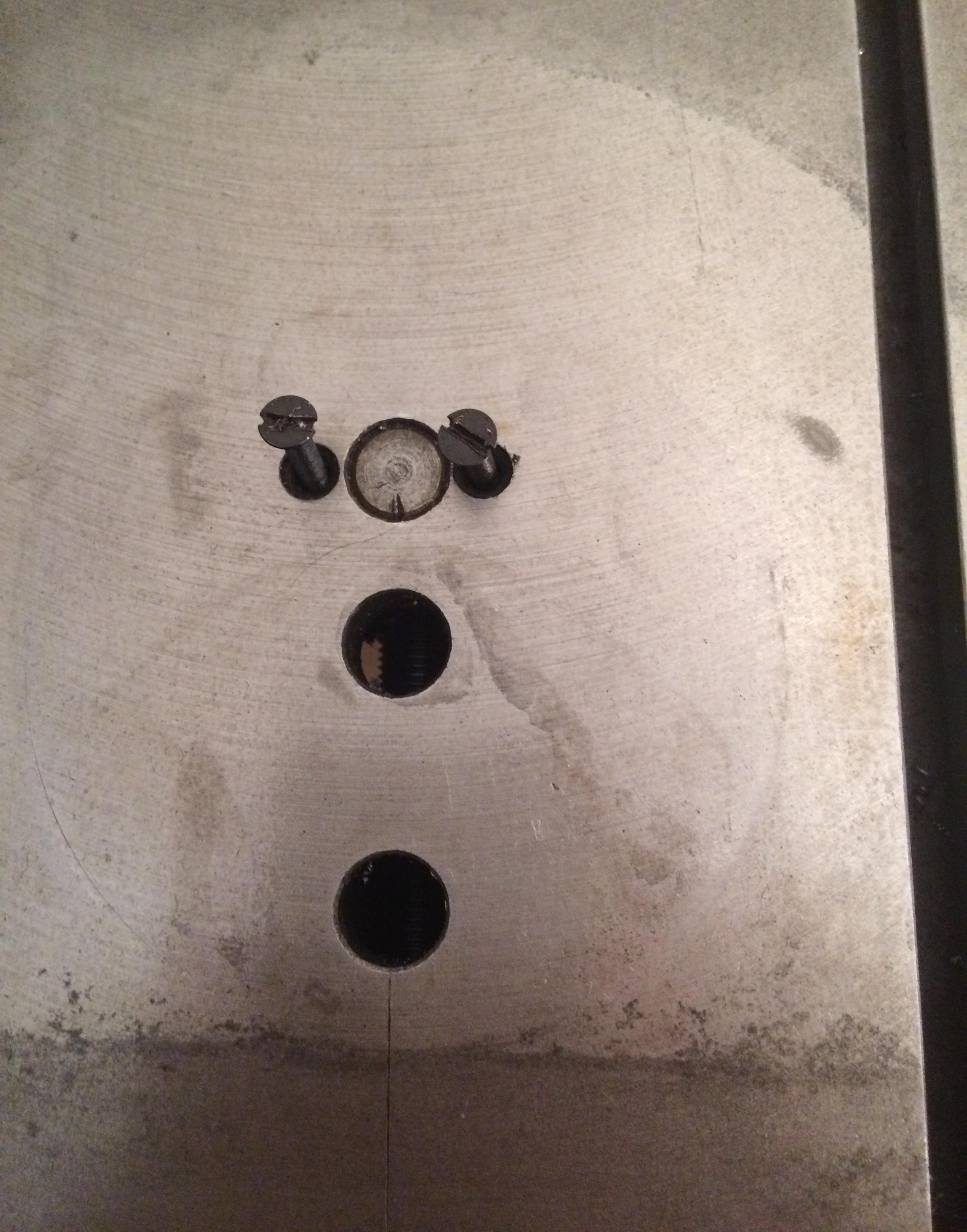
The cross-slide nut (M10x1 left-hand) is held to the cross slide by two M3 countersunk screws and has to come off so the cross slide can be removed and the apron’s innards accessed from above:
The cross-slide ways are worn about 5/100 mm at the front. The shoulder is detectable with a fingernail. For now, however, I want to work with the machine and get a feel for what’s still doable in the current state.
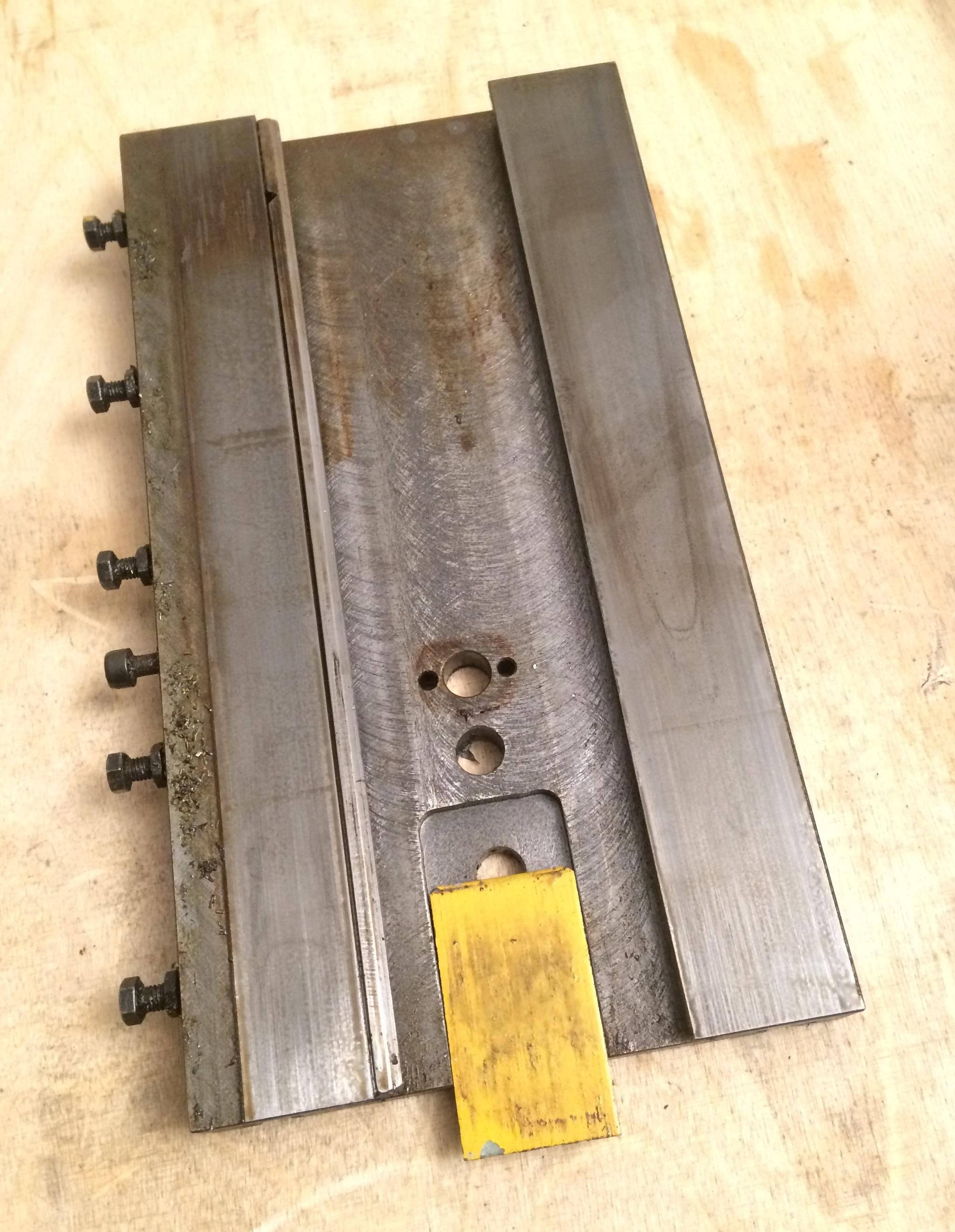
The saddle can now be unbolted from the apron:
Here, too, masses of old grease and chips show up:
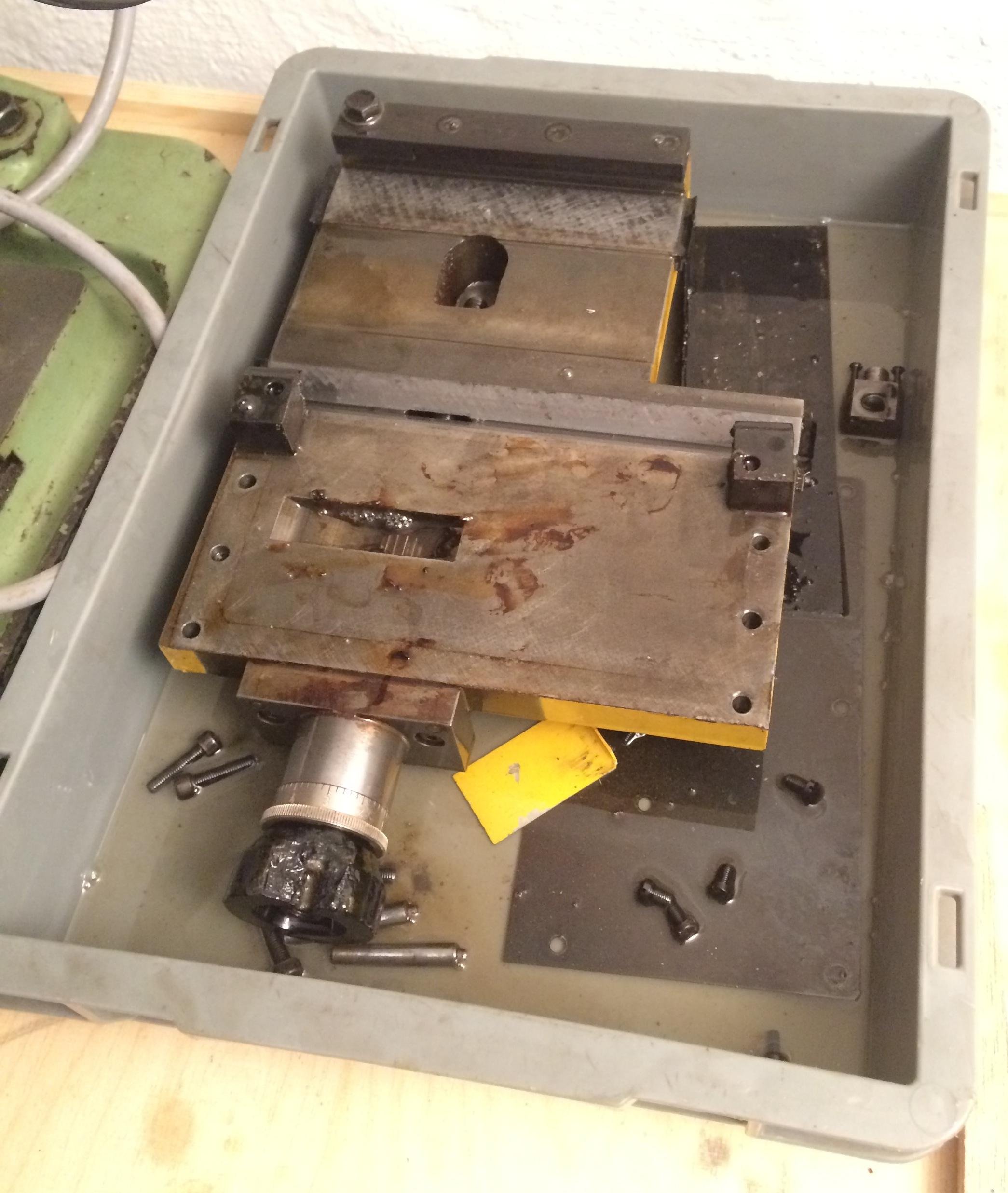
The unbolted parts go straight into the kerosene bath to soak:
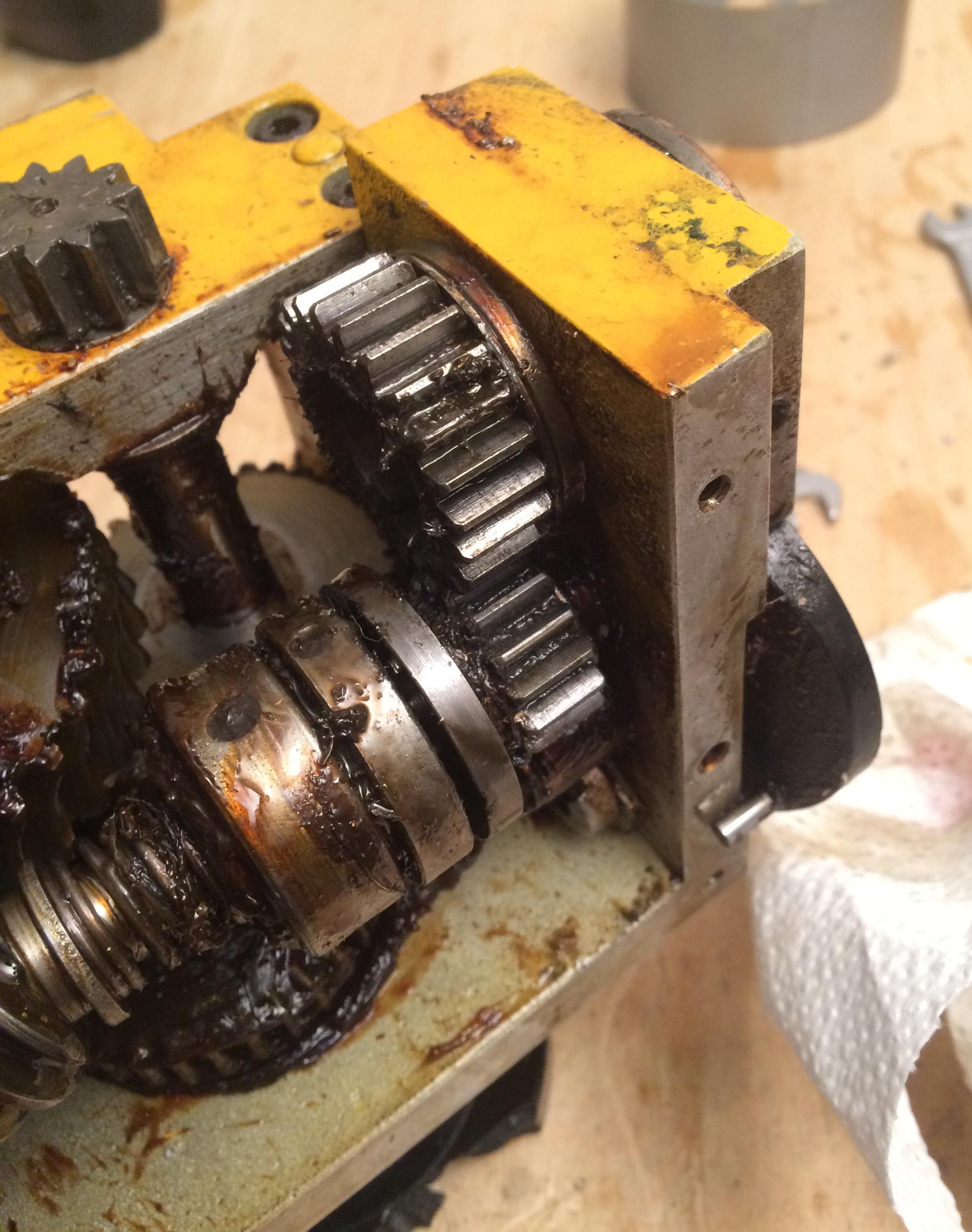
This also exposes the first reason for the gearbox’s binding. One tooth gap had been packed with chips and grease:
So, same game: soak in kerosene and brush off the worst of the muck:
Chips keep turning up in the most unlikely places:
Slowly, progress becomes visible:
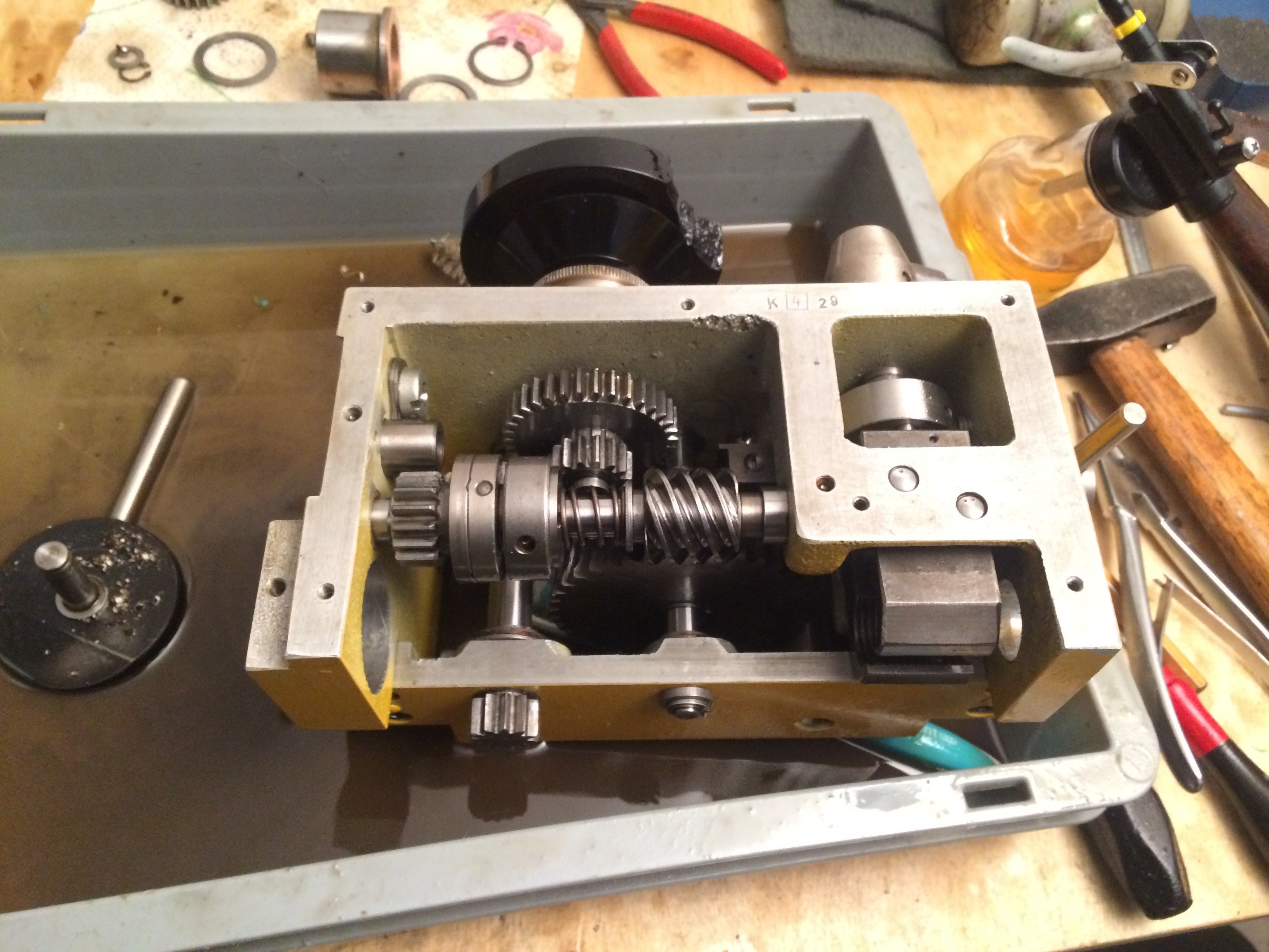
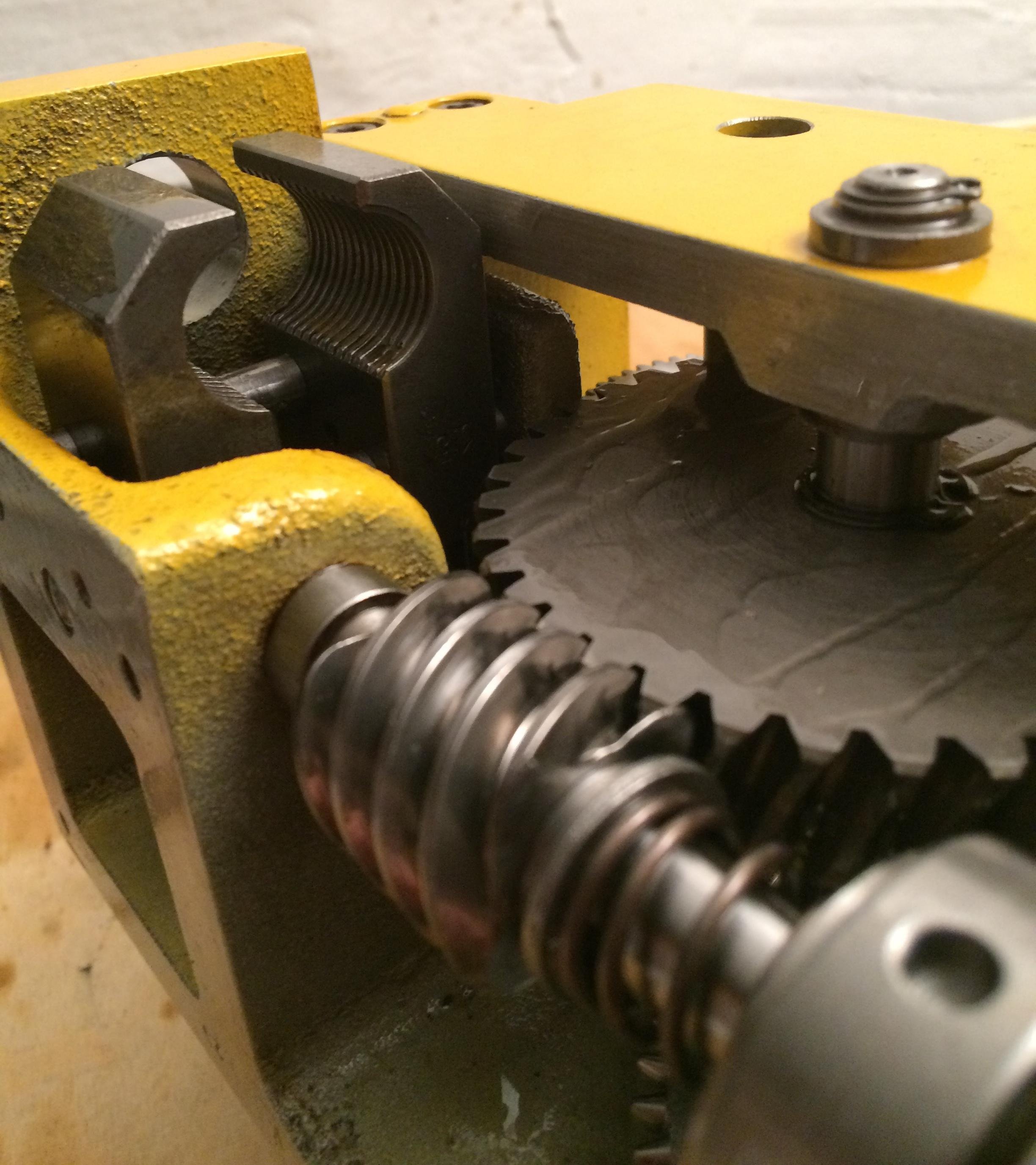
After what felt like endless cleaning, the inside is presentable again. The power flow is as follows: At the bottom-left in the picture, the combined leadscrew/feedshaft drives the whole mechanism. Through the first gear pair it goes to an overload clutch, which simultaneously also serves to engage the feed manually. From there, a four-start worm is driven, which is permanently in mesh with the large worm wheel.
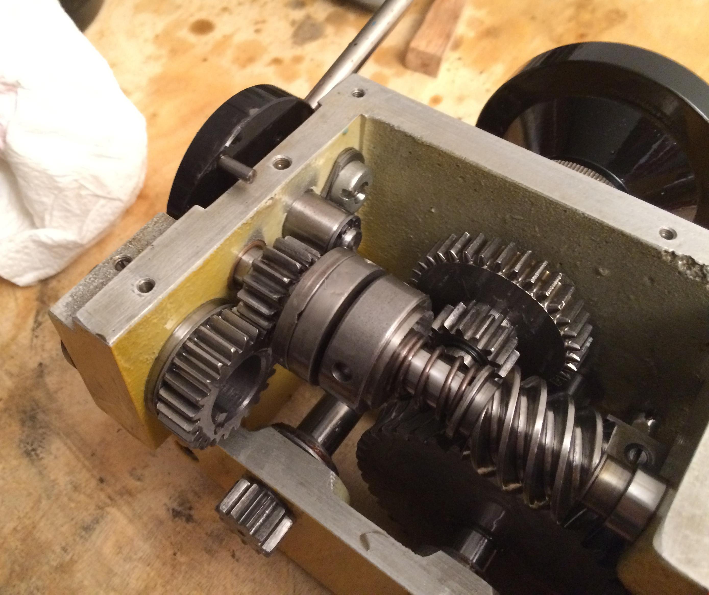
From the large worm wheel, power goes either through a dog clutch onto the cross-feed lead screw, or through a sliding gear onto the longitudinal feed (driven from the handwheel). In the picture the cross feed is currently engaged:
The leadscrew nut also still looks reasonably OK (apart from two small broken-out bits):
That concludes the cleaning of the apron, and we move on to the saddle:
Here too, after a bit of kerosene and Scotch-Brite, progress is visible:
A few small parts to clean and then we can start reassembly:
I’ve greased the gears in the apron with MoS2 grease for now:
The gearbox now turns by hand beautifully again, and the saddle slides along the bed beautifully too. Next up are the leadscrew bearing block and the repair of the leadscrew coupling piece, where the shear pin had sheared. Unfortunately someone had “fixed” the shear pin with a spring sleeve, and that left wonderful galling marks inside the leadscrew transition.
It’ll be doable…
Change gears #
The change gears of the DLZ180x450 are module 1 with a 20 mm bore. They have a keyway 4 mm wide and 1.8 mm deep (relative to the bore wall).
The change gears that came with mine:
with 8 mm tooth width and 10 mm hub width: 120 (M), 110 (M), 100 (P), 90 (M), 80 (M), 75 (P), 2 x 70 (P), 65 (P), 2 x 60 (P), 2 x 50 (P), 45 (M), 40 (P)
with 10 mm tooth width and 12.2 mm hub width: 32 (M), 30 (M)
(M) means the gears are milled from metal. (P) stands for injection-moulded plastic.
Electrical cabinet #
I recently finally had time to fit the VFD into a proper electrical cabinet.
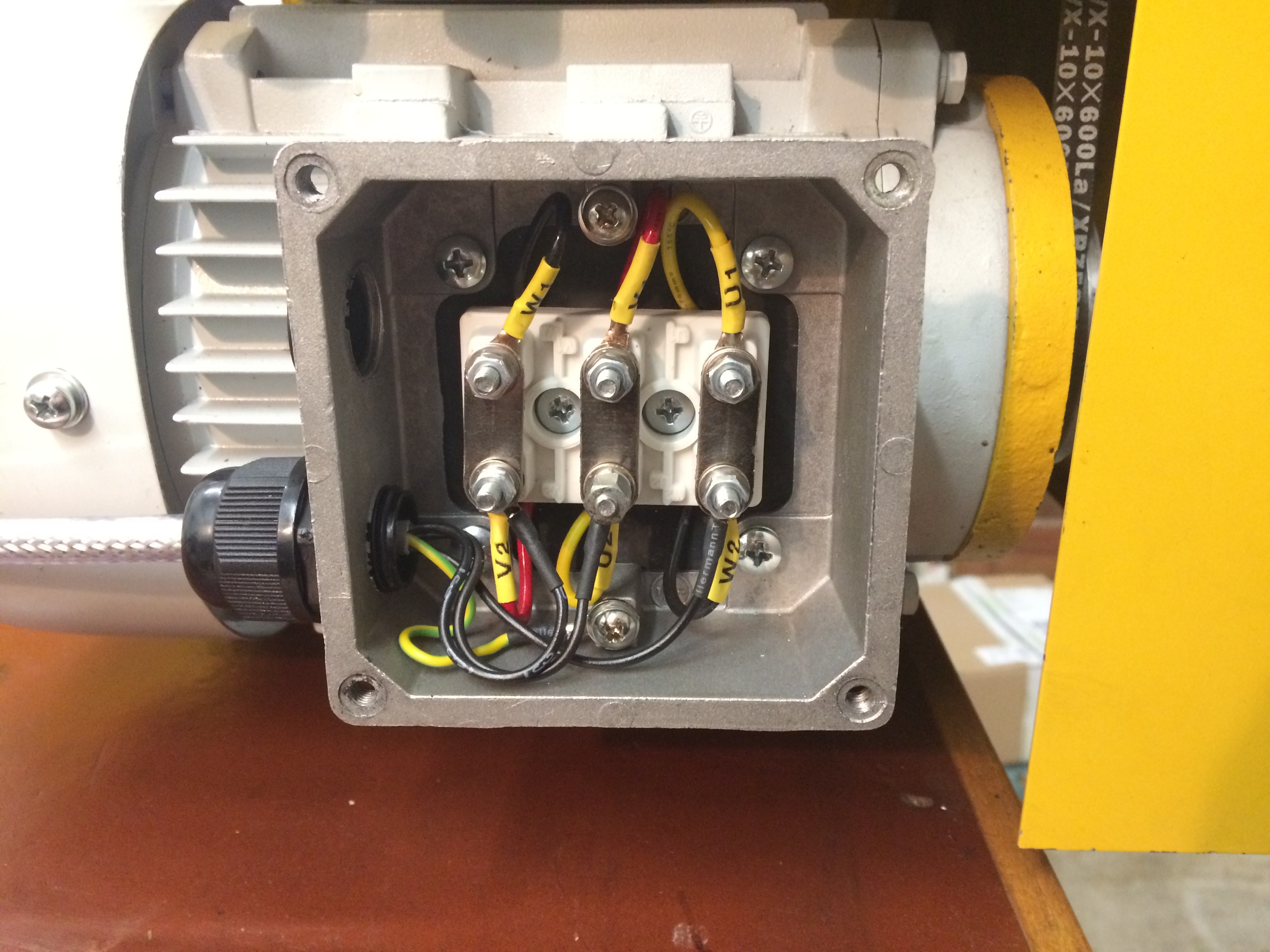
First, it was confirmed that the motor is still wired in delta:
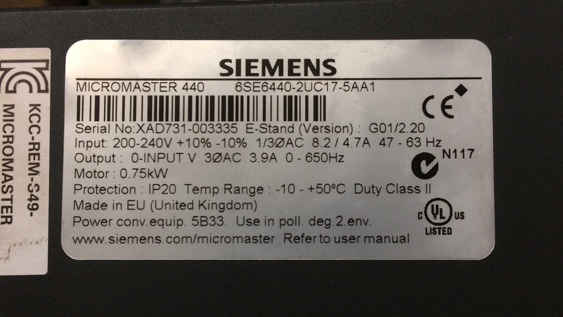
The VFD used is a Siemens Micromaster 440:
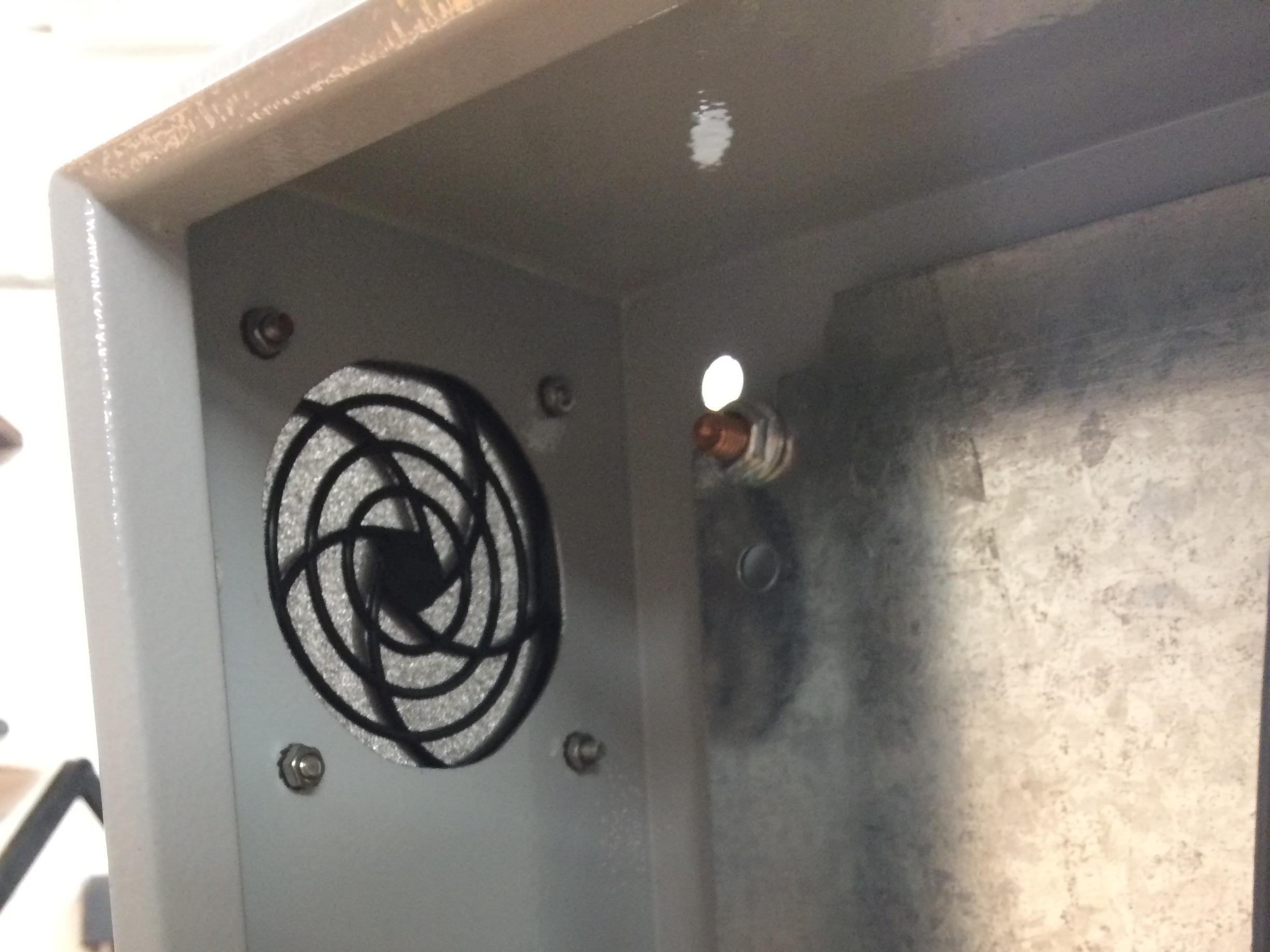
Here is the assembled cabinet:

There’s also a wiring diagram:
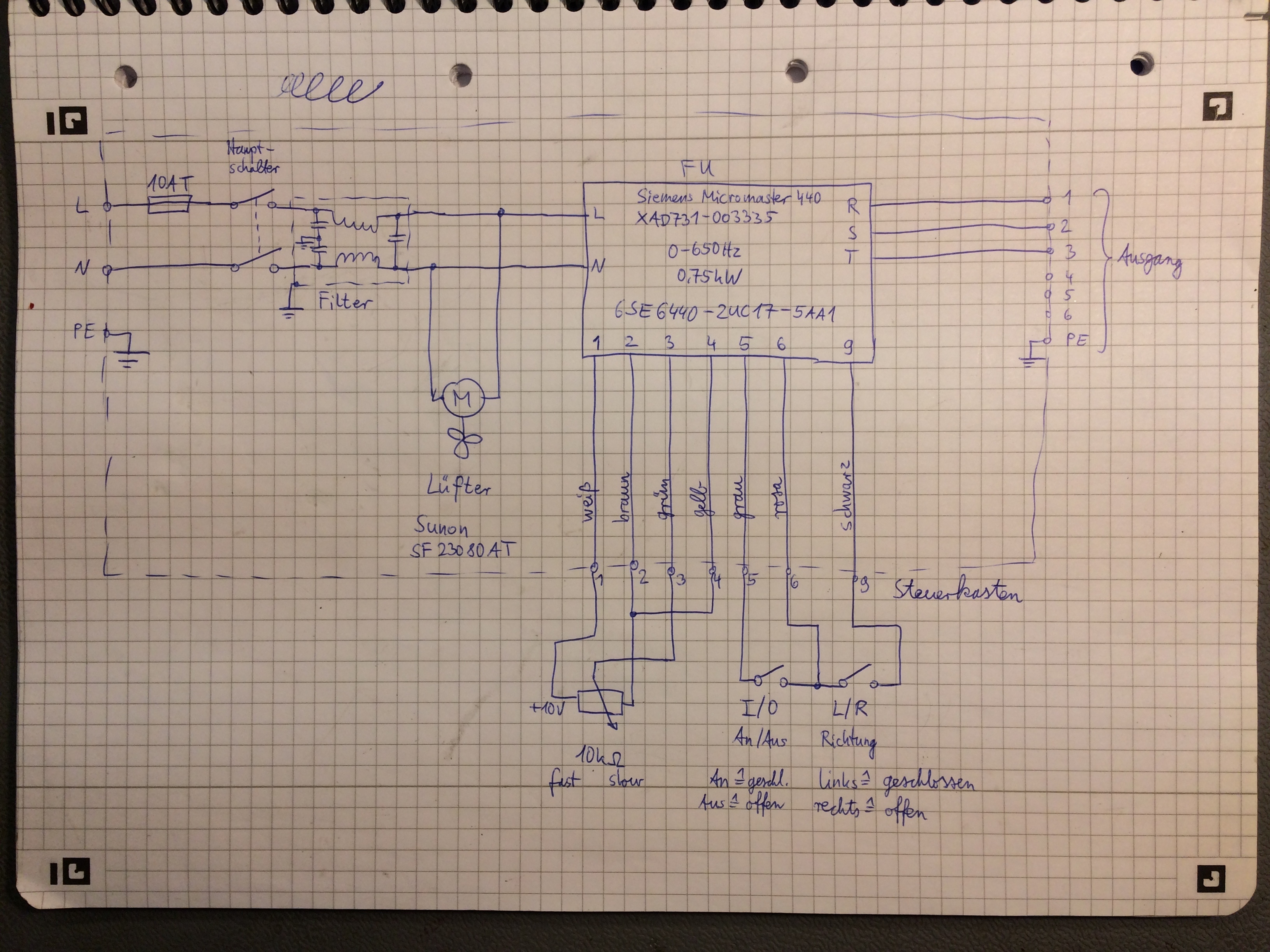
A fan blows fresh, filtered air into the cabinet at the bottom right.
It exits at the top left through another filter, so the VFD hopefully
doesn’t get too hot:
There may also be sense in retro-fitting a braking resistor at some point. There’s definitely room for it, and the resistor would sit “optimally” in the airflow.
I then bolted the cabinet to the wall next to the lathe:
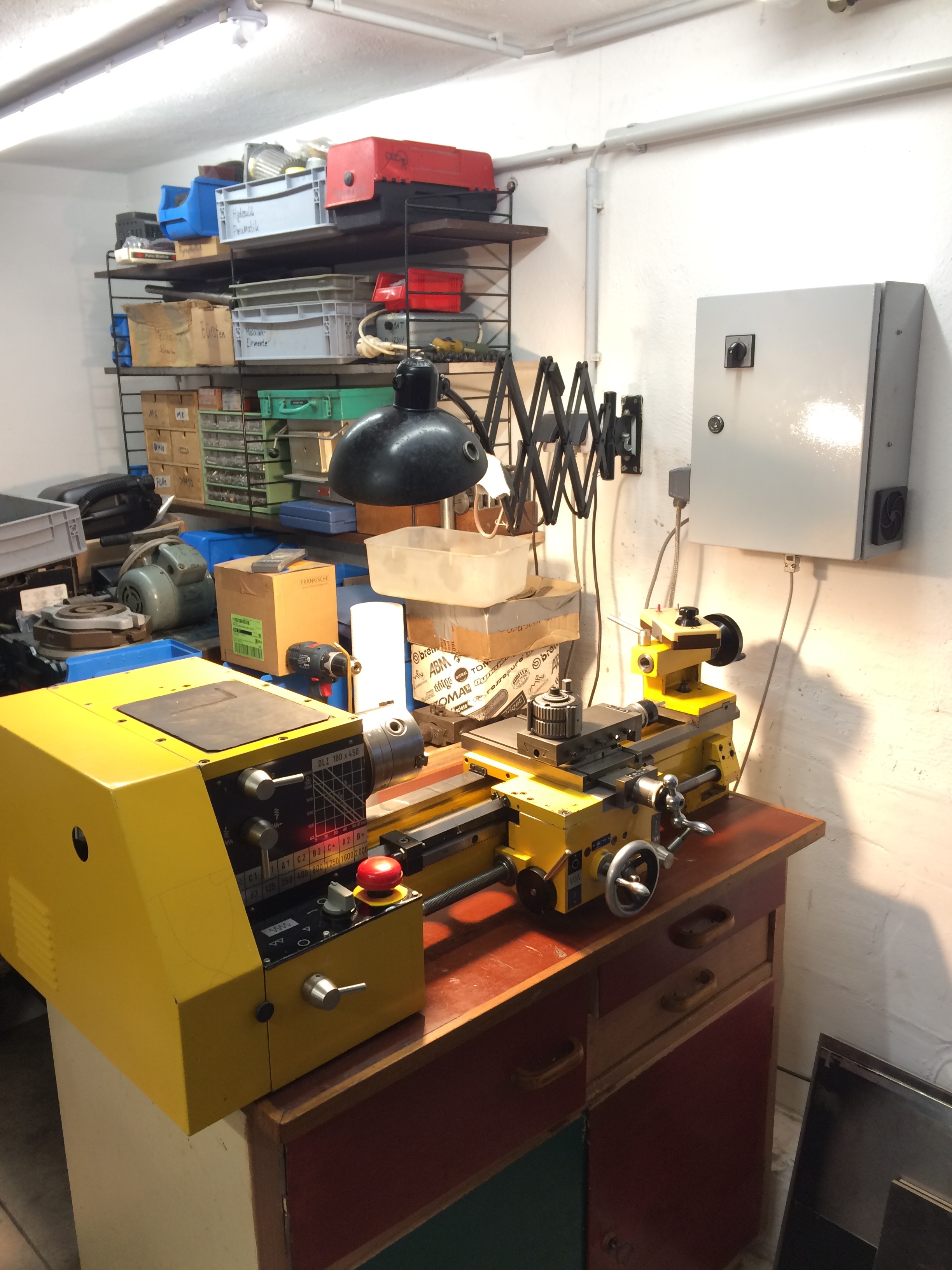
It’s quite something to now just need to turn the main switch and be ready to go :-)