From an old Sciex QStar XL time-of-flight mass spectrometer I was able to salvage a pulser module:
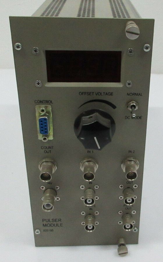
Alongside some nice components – MHV and SHV connectors, high-voltage relays and MOSFETs, and an OPA541 power op-amp – it also contains a switch-mode power supply that drives the gate drivers for the HV MOSFETs.
This page is about the area outlined in red on the two boards:
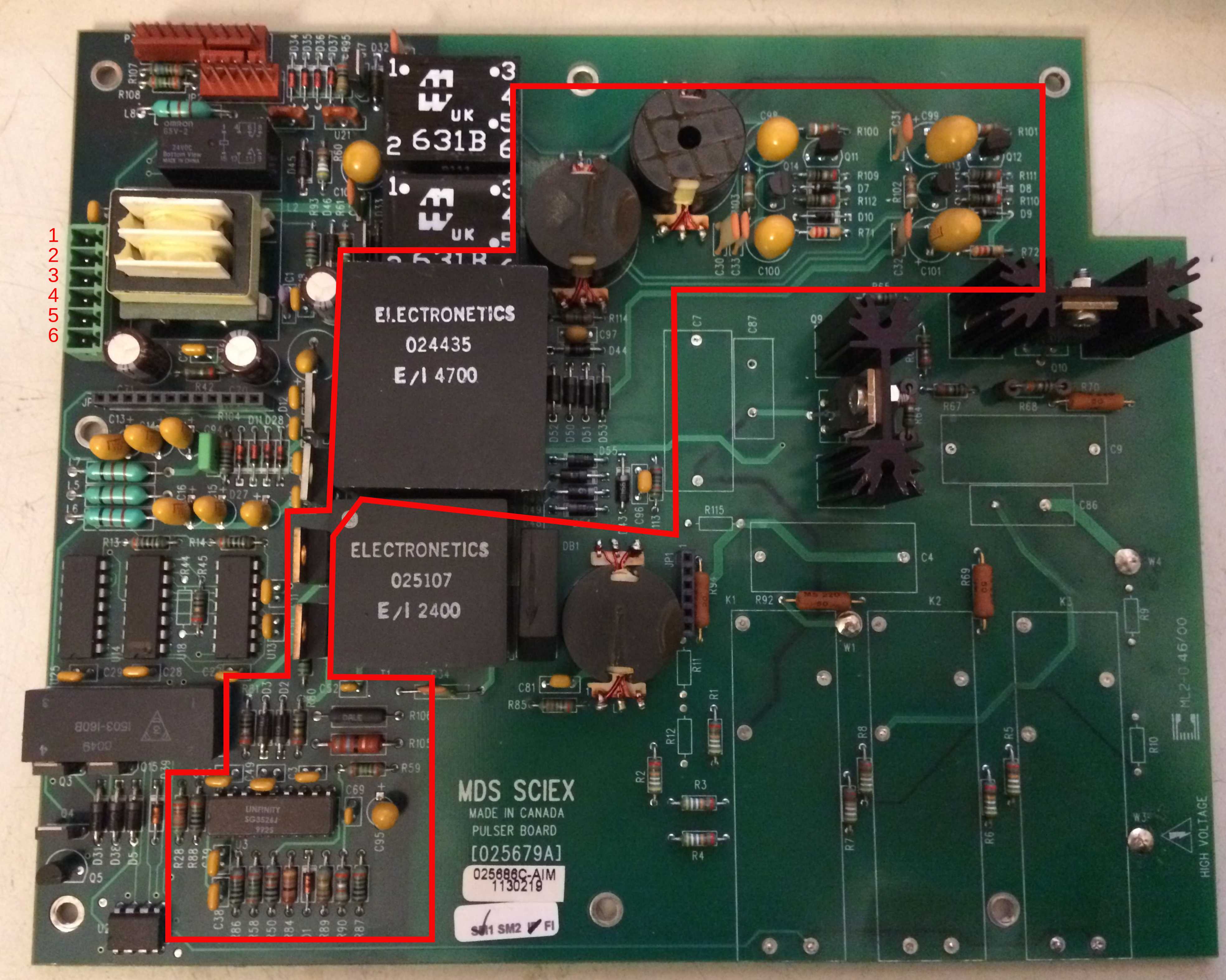
The controller IC used here is the SG3526J. The larger of the two transformers, labelled 024435, was made by Electronetics and is probably a custom part commissioned by Sciex.
The table below shows the wiring from the power-supply connector at the top left (pins 1-6) to the NIM connector:
| Pin on board | Wire colour | NIM pin | Function |
|---|---|---|---|
| 1 | yellow | 16 | +12V |
| 2 | white | 17 | -12V |
| 3 | red | 10 | +6V |
| 4 | blue | 28 | +24V |
| 5 | black | 34 | power GND |
| 6 | grey | 42 | high-quality GND |
If you now connect a 12V supply between pin 1 and pin 5, the switch-mode supply at least comes to life. It delivers a symmetric +/-15V for each of two gate drivers. For further testing, the gate-driver sections of the circuit were disconnected. Various load resistors were placed between +15V and -15V across the paralleled outputs. The resulting load curve is shown here:
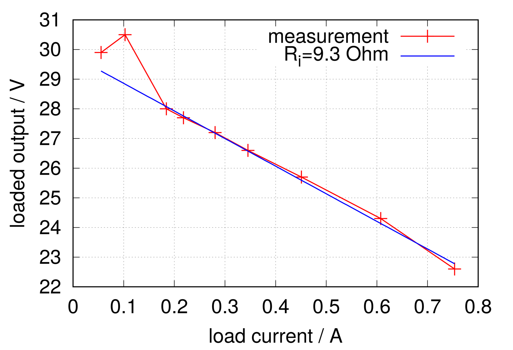
The model assumed is an ideal voltage source with a series (internal) resistance. The fit to the measurements (points with I<0.15A were ignored) gives an internal resistance of about 9.3 ohm at an open-circuit voltage of 29.7 V. A measurement under no load, however, yields an open-circuit voltage of around 70 V. The likely reason is that the SMPS topology used here has no feedback from the secondary side to the primary-side control.
The supply is interesting because its construction is fairly simple (= robust, easy to repair) and the isolation between the secondary and primary should be reasonably high-voltage-rated. Together with its usable rated output current, it might be suitable for driving the gates in a DRSSTC… ?